


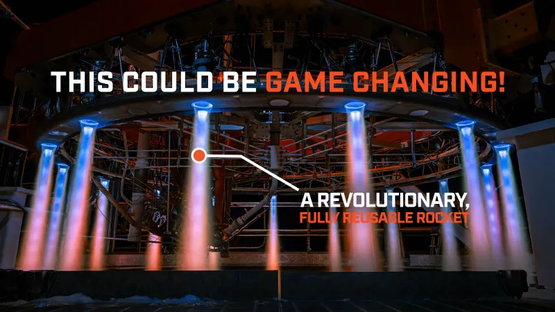
Riding the healthy “new space” wave, there are quite a few start-ups trying to get a portion of the space launch market. When such a company claims to be developing novel tech, something ground-breaking, hardware that will be fully reusable and game-changing, well, it is reasonable to err on the side of caution and remain skeptical. Stoke Space, however, is not only claiming this, but actually building and testing hardware accordingly to its claim, and at an amazing pace.
In this article, a companion to Everyday Astronaut’s video on Youtube, we tell you about this incredible company and the exciting concepts it is working on. We will break these topics down for those of you who favor learning through reading, or who simply find it to be a good complement.
The Company
Andy Lapsa, a former Blue Origin employee, is its CEO, and one of its co-founders. Actually, the company benefited from gathering people both from Jeff Bezos’ space venture as well as from SpaceX. In this opportunity, Andy was Tim’s host during the visit, and he explained that to achieve the company’s goals “you have to design, build, test, iterate; as fast as you can possibly do it.” In order to do that, it is necessary for it to be vertically integrated. This means that Stoke carries out a number of strategic stages of its operations by itself, without relying on external suppliers.
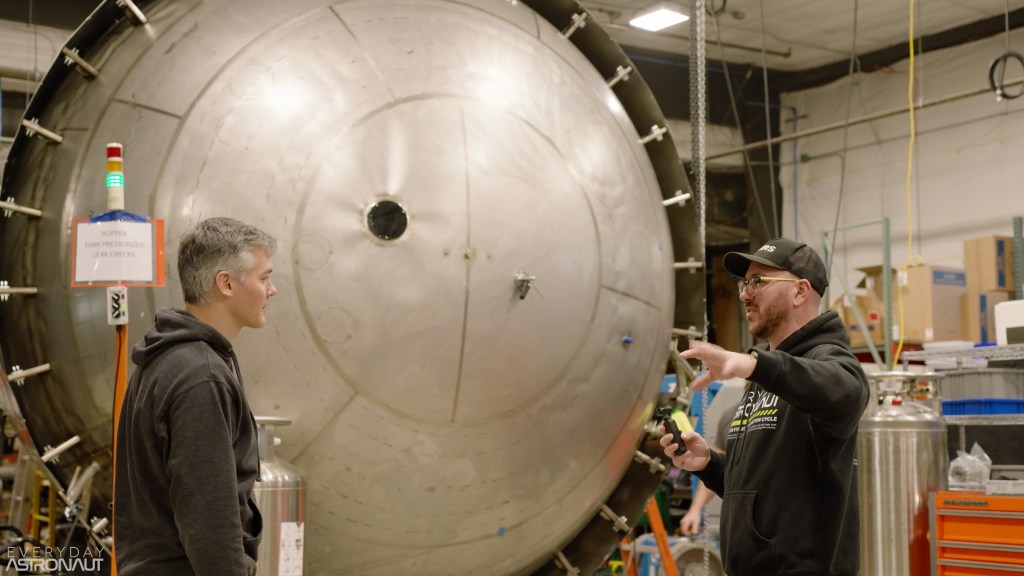
Based in Kent, Washington, its headquarters is where engineering and manufacturing take place. Because of the vertical integration approach, its workshop consists of machines that offer not only four-axis and five-axis machining capabilities, but also lathes, mills, and even electrical discharge machining. During the tour, the Everyday Astronaut witnessed firsthand all of the hardware being built there, and the exciting work the employees are doing.

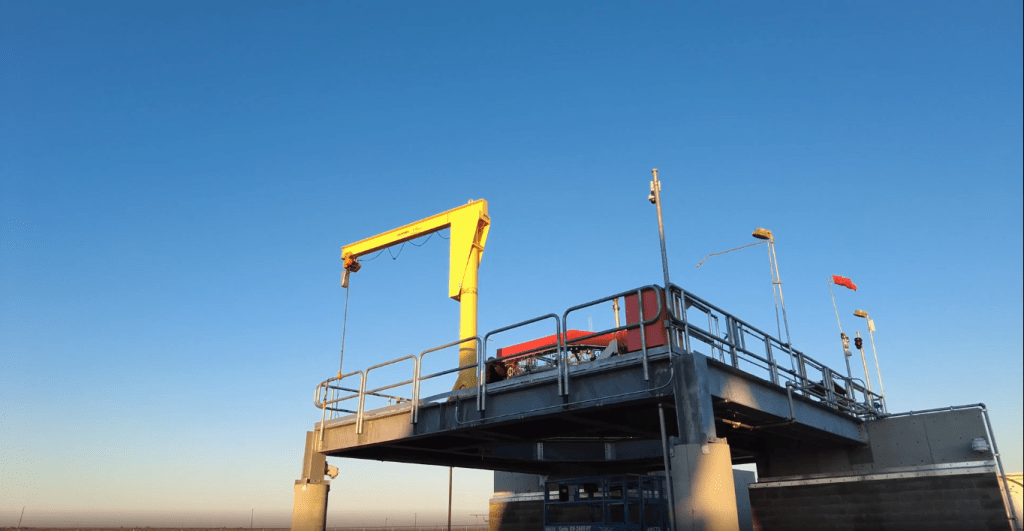
A second facility is designated for testing and is placed at a 3-hour car ride from Stoke Space’s headquarters. Located in Moses Lake, Washington, the area was ideal for these installations, as both Boeing and the US Air Force had projects running there in the past. Consequently, some infrastructure was still in place, and qualified workers related to the aerospace field lived there. What is more, these testing facilities lie next to an airport with humongous runways which served as a backup landing site for the Space Shuttle!
The company has built all of this in the 18 months prior to Tim’s visit in November 2022. Stoke follows the radical approach of going all in for 100% reusability.
Stoke’s Rocket
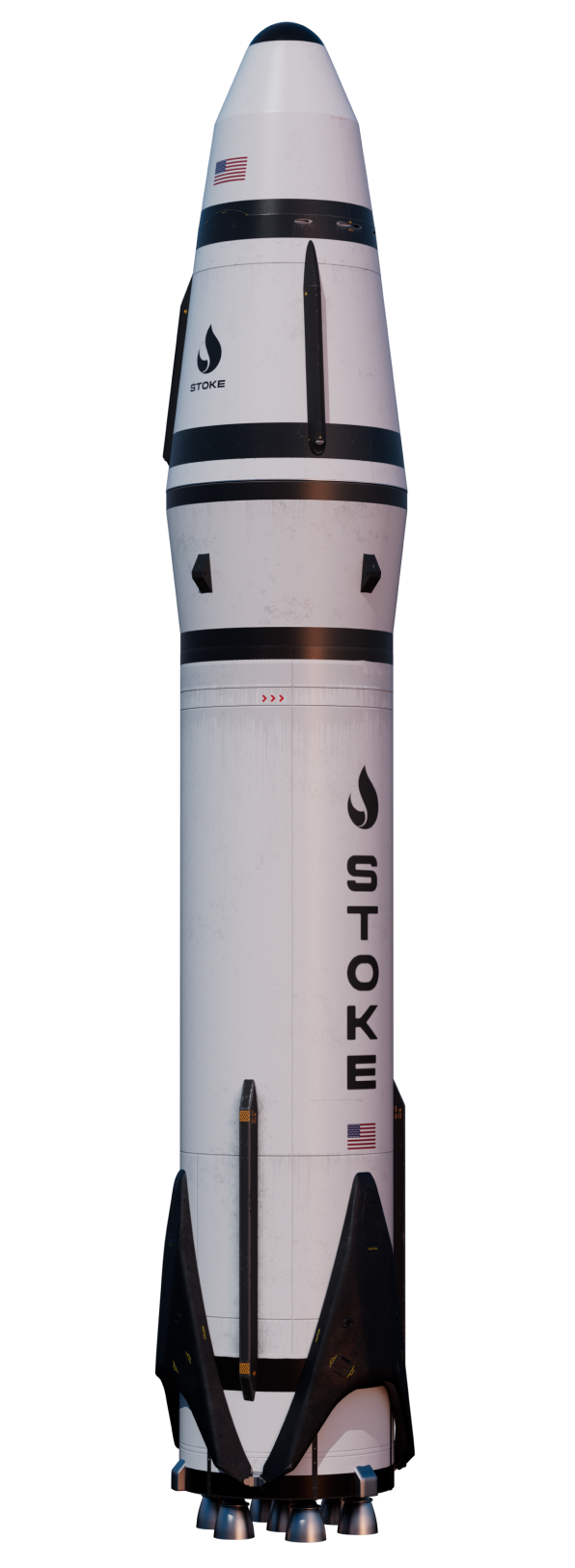
Stoke’s rocket is a two-stage vertical takeoff and vertical landing (VTOVL) vehicle, similar in principle to the Falcon 9’s first stage. Built from stainless steel, when fully stacked the vehicle will stand 30 meters tall and have a diameter of 4 meters.
The choice of using stainless steel as the material for the rocket was driven by both its manufacturability and its availability, with many suppliers offering the alloy, thus avoiding supply crunches. The selected (and unknown) alloy of stainless steel offers excellent material properties in the form of sheet metal, and it maintains properties even at high temperatures. Additionally, when compared to other materials for stage design there was not a large difference in vehicle performance. So, Stoke decided to focus on ease of manufacturing.
Second Stage
Stoke’s rocket’s second stage is designed with versatility in mind: it has the uncommon ability to acquire assets on orbit and bring them back to Earth, making it possible to deploy and move spacecraft around on orbit. Using a ballistic trajectory, the second stage is designed with a capsule-style reentry — the shape of the second stage is similar to a traditional capsule, with a tapered design from the base to the top — allowing for a precise landing. The engine on the second stage is capable of deep throttling, giving it the ability to perform a reentry burn and a terminal descent with a propulsive landing.
The loading of the second stage is restricted to the axial direction, which helps in reducing structural mass, as it does not need to resist lateral loads. Additionally, it makes it easier for payloads by preventing them from having to deal with changes in loading direction. In comparison, this is similar to what happened when the Space Launch System experienced strong lateral winds from Hurricane Ian and engineers were worried. This is due to the fact the rocket was designed to be hit by the air coming from its pointy end, not from its side. The non-gimbaling engine of the second stage also contributes to its structural efficiency.
Below its heat shield, the second stage is equipped with various systems such as turbo machinery, valves, pressuring bottles, avionics, and controls. The tanks used in the second stage are designed with landing tanks inside of them, with the landing burn using the smaller ones. By avoiding a belly flop, like SpaceX’s Starship, the second stage will remain vertical throughout the flight, minimizing the management of cryo fluids sloshing in the tanks.
The second stage will not be test flown atop another rocket due to difficulties in the interface with the lower stage, particularly with the unique engine design and the fact that it runs on LH2. However, the company still has LH2 mobile infrastructure, as they are building the upper stage hopper first. LH2 is not widely used by other companies but gives the performance Stoke needs for reuse of the upper stage. Despite being more expensive and harder to source, the use of LH2 betters the vehicle for reuse.
Stage 2 Engine
Stoke’s second stage engine is designed with structural efficiency in mind. The engine consists of a single expander bleed cycle turbo pump that currently has 15 thrust chambers. Long term, the engine will have 30 thrust chambers in a modular design. Each copper chamber is great for low-pressure efficiency — avoiding the need of a structural jacket, or reinforcement around it — and is fed by a single fuel turbopump, generating 1,000 horsepower. The LOx pump requires less power due to LOx being more dense than LH2.

Because the test engines have 15 chambers, Stoke gains chamber test time 15 times faster, allowing for more reliability. During the design process, Stoke considered gimballing engines, but the required ceramic seals that would work through many cycles seemed unreliable. Instead, steering is achieved through differential throttling. This led to the decision to use pintle injectors as they allow for deep throttling. Additionally, pintle injectors allow for propellant mixture to remain consistent throughout the throttle range. Due to this design, engine shutdown needs to occur simultaneously all around the entire ring of thrust chambers, preventing orientation changes caused by moments — i.e., some thrusters on one side firing longer than those on the opposite side. Finally, a pintle injector allows for a clean propellant injection shut-off, resulting in better simultaneous engine shutdown and better orbit insertion accuracy.

Stage 2 Heat Shield
The second stage’s heat shield is a dome-shaped structure connected to a cone, which is in turn connected to the shoulder where circular cutaways are located for the thrusters. During reentry, “cold” hydrogen (H2) will circulate behind the heat shield through propellant feed pipes, which will be used to spin up the pumps via the expander cycle. This takes energy from the heat shield to cool it down. The heat generated by air compression and plasma during reentry is absorbed by the H2, causing it to spin the pumps faster, circulate more propellant, and cool the heat shield. This creates a self-regulating system, at least to some extent. Both the heat shield and chambers are cooled down by the H2 during reentry.

The idea behind the design is to bury the second-stage engine within the heat shield; this allows them to put an active cooling system in the heat shield, which drove Stoke’s choice to use an engine that makes use of the aerospike effect. The heat shield has a skew angle and is not symmetrical, allowing it to provide a force that helps steer the vehicle during reentry. For example, and without loss of generality, if the heat shield protrudes more to the left it produces a force to the left.
Stage 1
The first stage of Stoke’s rocket will run on liquid methane (CH4) instead of LH2 due to it being more cost-effective. To further help this goal, the first stage’s engines will use the full flow staged combustion cycle, which allows for high chamber pressure and lower temperatures. This is ideal for reuse.
The first stage features a taper in its upper quarter, increasing its diameter up to the interface with the second stage. This helps during descent and landing as it moves the center of pressure downstream — that is, closer to the top of the stage — and increases the drag coefficient.
They plan to do an untethered hop test with the 2nd stage, but when ?
You say “makes use of the aerospike effect”, but could you please explain where the spike is? This looks like a bunch of small engines with no nozzle and no spike. Or are there small toroidal spikes hidden in each of those holes?
I think I’ve found the answer here:
https://patents.google.com/patent/US20210381469A1/en?q=(stoke+space)&assignee=Stoke+Space+Technologies%2c+Inc.&sort=new
The link to patents.google.com is good as is this photo on twitter. The heat shield is the [truncated] spike: https://twitter.com/stoke_space/status/1623730283093827585
Do we have a feel for what the dry to wet mass ratio might be for the return vehicle?
Well done Tim. This is a really well produced introduction to a very interesting company with a great, innovative product. I hope we will hear a lot more about these guys.
“Moment” as in the moment arm, as in a torque or torsion created by the unfortunately coincidentally chosen description of “momentary” thrust imbalance. If all thrust chambers don’t extinguish simultaneously, a twist is applied in one plane or another, due to an applied “moment”, or a force applied at some distance from the axis of rotation. The “moment” Stoke is referring to is not a momentary difference in thrust balance, though that is what would create what engineers call a “moment”.