


Introduction
Rocket engines are incredibly complex machines, pushing the boundaries of materials science and human ingenuity, with a multitude of different engine cycles that characterize the engine. In this article we discuss the many rocket engine cycles that engineers have used.
The types of power cycle range from very simple cycle types like cold gas thrusters, to more and more complicated ones like the famous full-flow staged combustion. This article will showcase all prominent types of engine cycles and describe and picture them in detail.
We can compare rocket engine cycle types to internal combustion engine types, in one sense. Car engine types include 2-stroke, 2 cylinder, or 4-stroke, 4 cylinder, supercharged, turbocharged, etc. They all operate under the same basic principles but employ different techniques to reach their power and/or efficiency goal.
Some of the following will sound familiar if you’ve read or have seen our article and video about SpaceX’ Raptor engine, but this time the whole article and the video will only focus on engine cycle types.
This article is also available in the form of a video on our YouTube channel Everyday Astronaut.
Requirements And Basic Principles
Please view our previous article or video about why rocket engines don’t melt before reading this article. We mention some of those cooling principles discussed in that article/video. It provides a great base knowledge of how rocket engines work, which will help you to better understand the following. We will produce even more articles and videos about how rocket engines work in the future.
Newton’s 3rd law of motion dictates how a rocket engine functions. For every action, there is an equal and opposite reaction. So, an engine expels some mass out of one end. The result is that the whole vehicle propels itself in the opposite direction. The faster and more matter that the engine expels, the greater the efficiency and the higher the thrust. The more thrust that the engine produces, the more payload the rocket can deliver.
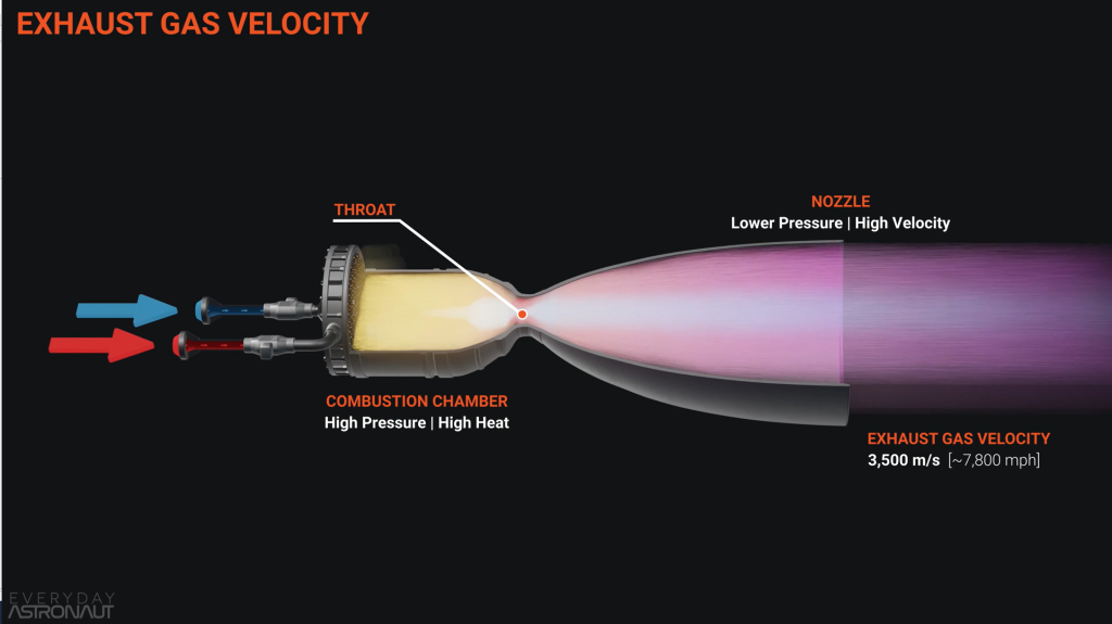
Engineers refer to the speed of the nozzle exhaust as exhaust gas velocity. This velocity not only correlates to the thrust that the vehicle generates, but also correlates with the efficiency of the engine. The faster the engine pushes the exhaust gas out of the nozzle, the more efficient this engine is.
Combustion Chamber And Rocket Nozzle
We convert pressure and heat inside the combustion chamber of a rocket engine into kinetic energy. This is done using a so-called de Laval nozzle, or a convergent-divergent nozzle. The nozzle which converts hot subsonic high-pressure gas into cooler supersonic lower-pressure gas.
The challenge here is to get the pressure and temperature inside of the engine as high as possible. All this while managing the heat. Heat and pressure give high performance, but can be difficult to contain and manage. Generally speaking, the higher the temperature inside the combustion chamber, the better, as heat is proportional to energy.
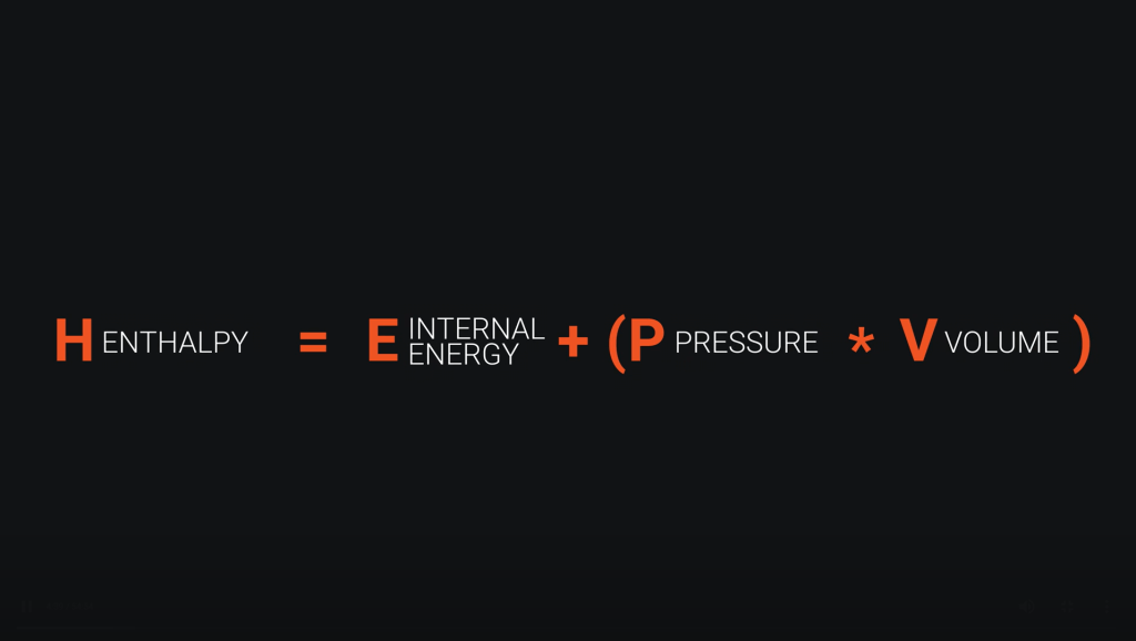
At this point, we have to introduce the term enthalpy. Enthalpy is the sum of all energy that a system contains. Specifically, enthalpy is the volume times the pressure plus its internal energy. The internal energy in this case consists of heat and microscopic kinetic energy. The higher the enthalpy in the system, the more potential it has to perform work.
Another important rule to know is that high pressure always flows to low pressure. In the case of rocket engines, it means that the goal is to have high pressure in the combustion chamber. This is to expel the exhaust gases as fast as possible.
Cold Gas Thrusters
The simplest form of a rocket engine just stores some sort of propellant in a tank at high pressure. Then, open a valve, and let that high pressure flow out through the engine. This is the basis of cold gas thrusters.
As the name suggests, these engines run cold, meaning that there is no chemical reaction or combustion taking place. The simple expansion of a stored gas through the nozzle is what provides thrust in these types of engines. The term “cold” in these engines comes from the fact that when gasses expand, the temperature drops as a result. Engineers call this effect the Joule-Thomson effect.
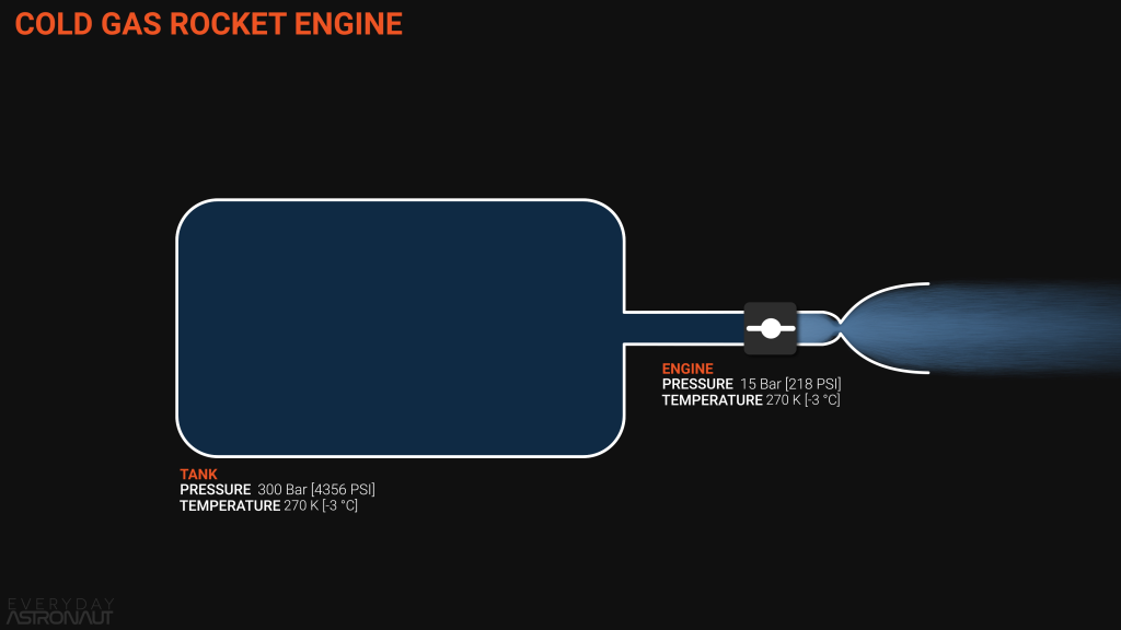
The biggest limitation of cold gas thrusters is the available pressure in the system and the lack of heat. Now, pressure always flows from high to low. So we want to store the propellant at the highest possible pressure. We also want to store as much as possible inside the tank. With higher and higher pressures, the walls of the tanks also have to become thicker and thicker . This makes them heavier, which is the opposite of what engineers always want to achieve in rocketry.
The goal of engineers is to store as much propellant at the highest possible pressure in the lightest possible tank. One way of doing this is by using so-called COPVs, or composite over-wrapped pressure vessels. Those COPVs are metal tanks, wrapped by composites like carbon fiber or Kevlar. COPVs typically operate at pressures of around 300 to 400 bar with some even reaching 800 bar.
Cold Gas Thruster Pressure
Propellant tanks for most of those kinds of engines store the propellants in a gaseous form. Nitrous oxide or butane are examples of exceptions to this. Tanks can store them in liquid form under high pressure. With most propellants being sparse, the tanks must hold even higher pressures. This means that the tanks need to be heavier too, resulting in a bad runaway effect.
Cold gas thrusters usually use helium or nitrogen for their high compressibility and relatively low molecular weight. Such gases are easier to accelerate. It would be possible to use hydrogen or some other propellants. So far no-one has done this in a well-known prominent example.
Since both pressure and temperature are low in this system, the specific impulse is also low. The the simplest and most basic pressure-fed engine has only about 60 s of specific impulse, or ISP. However, it is already three to four times more efficient.
There is another limitation of cold gas thrusters. The nozzle can only expand so far before the gas turns into a liquid while still in the nozzle. This is in addition to the overall lack of enthalpy in the system. However, cold gas thrusters are extremely simple and reliable. They only have one moving part – a valve. This makes this design a great choice for many small spacecrafts like small satellites or CubeSats.
Examples
Other examples of cold gas thrusters would be the little maneuvering thrusters on SpaceX’ Falcon 9 interstage. These help to reorient and guide the rocket for re-entry and towards its landing spot.
NASA’s Manned Maneuvering Unit, or MMU, also used cold gas thrusters on its three Space Shuttle missions. It had 24 cold gas thrusters paired with two tanks of 18 kg of gaseous nitrogen. This provided around 40 m/s of delta-V.

Pressure-Fed Engines
The pressure-fed engine cycle is the next most simple engine design. Similar to cold gas thrusters, pressure-fed engines have almost no moving parts. At the same time the offer much higher performance than cold gas thrusters.
There are two types of pressure-fed engines – monopropellant pressure-fed engines and bipropellant pressure-fed engines. They differ in the number of propellants they use. As the names already suggest, monopropellant pressure-fed engines use only one propellant, while bipropellant pressure-fed engines use two different propellants.
Monopropellant Pressure-Fed Engines
A monopropellant pressure-fed engine, or (for short) monoprop pressure-fed engine, is very similar to a cold gas thruster. The engine still has one tank filled with high-pressure inert gas. However, in addition, there is also a low-pressure tank with propellant, often hydrazine.
Monoprop engines open the valve from the propellant tank to the engine, while maintaining the pressure inside the propellant tank. They also modulate another valve between the high-pressure tank and the propellant tank. This high pressure tank holds an inert gas like nitrogen or helium.
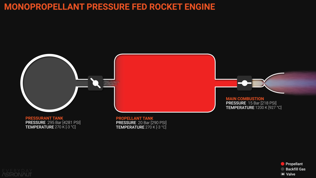
Monoprop engines are more efficient than cold gas thrusters. This is because they harness some chemical energy from the used propellant by running it over a catalyst bed. Hydrazine is one of the most common monopropellants. It flows through an iridium-infused alumina bed, which is a strong reducing agent. The resulting reaction converts the chemical energy in hydrazine to heat and pressure. The engine nozzle then expels this pressure as hot gas.
Composite Overwrapped Pressure Vessels
The COPVs keep the propellant tank’s pressure high enough. The COPVs constantly backfill the emptying propellant tank. This forces the propellant into the catalyst bed (since high pressure flows to low pressure). This allows storage of more dense liquids that don’t require storage at extreme pressures. Tanks can then hold large masses of such liquids.
Usage of more dense liquid propellants results in higher efficiency, compared with the sparse gases from cold gas thrusters. This leads to much smaller tanks for the same mass of fuel. The result is about three times higher specific impulse than for cold gas thrusters. So, monoprop pressure-fed engines are a great choice for reaction control thrusters (RCS). Spacecraft use RCS for attitude control and fine translation. Such engines are also great when simplicity and reliability matter most.
Prominent examples of such monoprop thrusters are reaction control thrusters on many satellites. Additionally, the reaction control thrusters on the Soyuz spacecraft uses H2O2 as fuel.
Bipropellant Pressure-Fed Engines
Bipropellant pressure-fed engines, (or for short, biprop) pressure-fed engines, are basically the same as monoprop engines. The difference is, as the name already suggests, a pair of both fuel and pressurant tanks. One set stores the fuel, while the other one stores the oxidizer.
They still work with the same principle as monoprop engines and cold gas thrusters. This is that the only moving parts are simple valves. The difference to monoprop engines is that those engines can use more energetic and efficient propellants. Examples of such are RP-1 and LOx, or even CH4 and LOx. Most bipropellant systems will utilize hypergolic propellants for their simplicity. Hypergolic propellants are propellants that spontaneously combust upon contact with each other. Any system using hypergolics is extremely simple and reliable since it requires no ignition source. Such a system still offers decent performance.
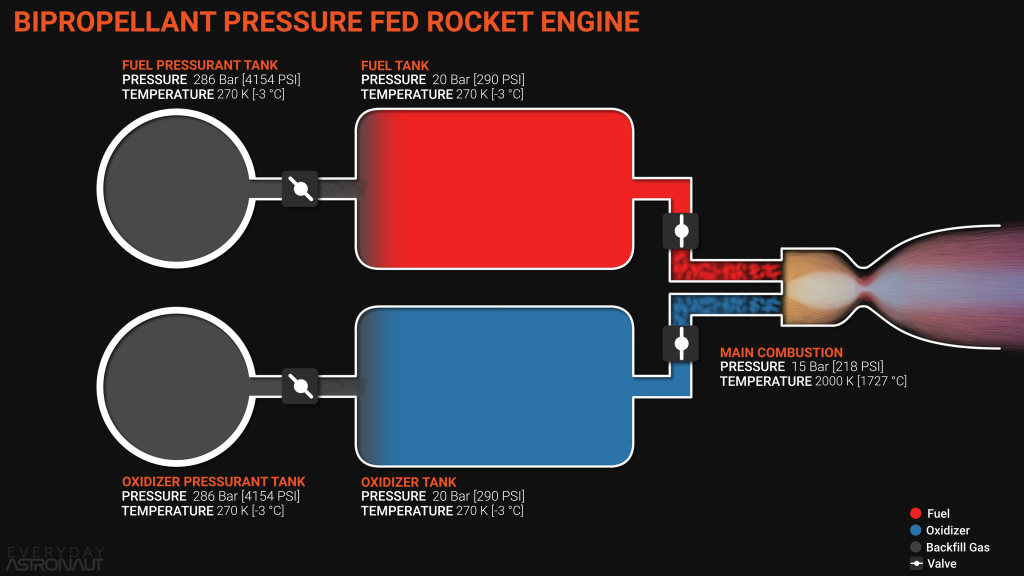
A problem here is the overall pressure in the system, meaning that the pressurant tanks are still the limiting factor. This is similar to what we saw with with cold gas thrusters and monopropellant pressure-fed engines. There is a trade-off where increasing pressure in the system increases weight. Too much additional weight ends up taking away more payload capacity than the increase in performance would add to it.
This helps to explain why we have never seen a purely pressure-fed orbital rocket. By that, we mean that all stages would be powered by pressure-fed engines. It is basically impossible to reach orbit with only pressure-fed engines due to their limited overall performance. This is true even with the newest and state of the art technology, such as carbon composite tanks.
Examples
We usually see pressure-fed engines on the upper stages of rockets. Some prominent examples include:
- SpaceX’ Falcon 1’s upper stage with its Kestrel engine
- Astra’s second stage Aether engine
- or the Space Shuttle’s Orbital Maneuvering System (OMS) which used the AJ10-190 engine.
So launch vehicles do not commonly use pressure-fed engines. However, nearly every US American spacecraft uses them. Examples include the Space Shuttle Orbiter, SpaceX’ Crew Dragon capsule, the Apollo Command and Service Module, and the Gemini capsules.
Electric Pump-Fed Engine Cycle
So far in this article, natural pressure in the tanks pushes the propellants into the combustion chamber. This places a natural limit on the chamber pressure. Gases and fluids can only flow by themselves from a high pressure to a lower pressure.
Suppose we want to obtain a higher chamber pressure without increasing the propellant tank pressures. Then our rocket needs to use some form of active mechanism to force the propellants (against nature). This could allow a higher pressure in the combustion chamber than in the tanks.
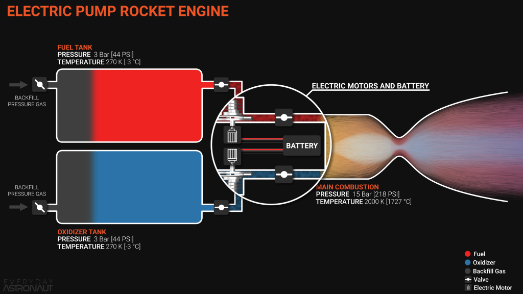
This is where pumps come in. We can use a pump to increase the pressure after the pump, without affecting the pressure before the pump. This is good news for rockets. So a pressure-fed engine might need a tank pressure of 30 bar. An equivalent pump-fed engine might only need a tank pressure of only 3 bar. This saves an enormous amount of mass for the tank. We almost certainly save more mass than we gain for the pump and related items. We can drive pumps using any source of energy, in principle. Let us first consider electric motors driven by battery storage.
Pump Power Requirements
Pumps can require a lot of power to operate as desired, sometimes in the order of 1000s of horsepower. As an example, the RD-170’s pumps require 230,000 horsepower.
By comparison, a Lucid Air’s motor unit can produce about 500 kW. This takes a mass of around 74 kg. Consider using these motors to drive the pumps on the RD-170. We would need about 340 of these motors. At 74 kg mass per unit, this represents over 25,000 kg just for the motors. This is over two and a half times heavier than the RD-170 engine itself.
This demonstrates that battery storage and electric motors, as an overall pump driver, does not scale well. However, it may be effective for much smaller pumps.
In fact, Rocket Lab has used electric-driven motors on their Electron rocket to pump propellants into their Rutherford engines. Since then, Astra has also opted to use electric motors to power their Delphin engines. Other small launcher start-ups are also looking to use this same approach. At the time of writing none has reached the launch pad, however.
We may find it necessary to jettison any depleted battery modules. In doing so, we can switch over to fresh unused batteries. This can save mass that we longer require. This helps to show why the industry has not used electric pump-fed engines more widely.
Open Cycle (Gas Generator)
We mentioned earlier that pumps can generally require a lot of energy. Pumps must run fast enough to push the propellants into the combustion chamber at the required pressure.
Battery energy density is lower than hydrocarbon energy density, for the right type of fuel. So it is possible to burn some of the propellant in a smaller combustion chamber, generating exhaust gases. We can pass these exhaust gasses over the turbine that spins the pump, to generate the required power.
This is the basis of the open cycle, also known as the gas generator cycle. The German-designed V-2 rocket, powering the A4 engine, was an early example of this. To drive the pumps on the engine, they did not use any of the propellants in the main tanks. Instead, they used a high concentration of hydrogen peroxide, H2O2 (which is rich in oxygen). They passed this over a catalyst of potassium permanganate pellets. This triggered a chemical reaction that produced heat and steam at high pressure. This steam had enough energy to spin the turbine that drove the pumps at the right speed.

The Mercury Redstone rocket also used this technique. It is still in use today on the Soyuz rocket, powering the RD-107A and RD-108A engines. However there is an inefficiency here. We have separate propellant systems for the gas generator than for the main engines.
Open Cycle Using Regular Propellants
It is better to take small amounts of propellant from the main tanks. Then pass these propellants into the gas generator. This generates high-pressure exhaust, which drives the turbine to power the pumps. In practice, this takes more fuel than ideal amounts of oxidizer. (That is, ideal for the chemical reaction to be most efficient.) This is fuel-rich combustion, and this reduces the temperature in the gas generator. Such temperature reduction is extremely helpful to ensure that the turbine does not melt.
The gas generator is fed from the pumps – but this raises a question. The gas generator powers the pumps – OK. But now we claim that pumps feed the gas generator. How can we start this process in the first place?
How to start a rocket engine is a topic for a future video. For now, at gas generator start-up, it is typical to point a separate cold-gas thruster at the turbine. This thruster only needs to operate very briefly before the gas generator operation can become self-sustaining. Usually engines use helium as the cold gas. The technique is known as a “helium spin start”.
Gas Generator Exhaust Products
The gas generator cycle exhaust products pass over the turbine first. Then they are expelled to the atmosphere, or vacuum, depending on which flight regime is active. The main combustion chamber does not use these products, and in fact it does not meet them. This explains the name of the open cycle.
There is a major disadvantage of the open cycle. It leaves a lot of unburnt fuel in the gas generator’s exhaust plume. We can see this on many rocket engines, most clearly on a Falcon 9. Engineers usually consider this wastage is acceptable as a trade for the simplicity of the open cycle is fairly simple. Any amount of wasted fuel is small compared to the total amount of fuel in the main tank.
Several examples of gas generator engines include:
- the Merlin 1D engine on the Falcon 9 as just mentioned
- the F-1 and J-2 engines used on the Saturn V rocket
- the RD-107A and RD-108A engines on the Soyuz, also as previously mentioned
- and the RD-68 engine on the Delta IV Heavy.
There are many others beyond this short list, but we need to move on to discuss other cycles.
Suppose there is not enough performance from the gas generator cycle to achieve the desired results. This would be due to that little amount of wasted fuel mentioned earlier. Can we do better?
Closed (Staged Combustion) Engine Cycle
The closed, or staged-combustion, cycle is a more highly developed approach to try to make use of the combustion products that are dumped overboard on the open cycle.
It is not as simple as merely attaching the exhaust from the gas generator to the main combustion chamber, and passing all the gas generator combustion products into the main chamber. This would have several disadvantages that would be very problematic very soon into flight.
The pressure that drives the turbine is usually kept as low as possible, and the pressure downstream from the turbine is lower than upstream of the turbine. As a result, the pressure in the exhaust pipe would be lower than that of the main combustion chamber. This would result in combustion chamber gasses flowing back up the exhaust pipe. This would be the opposite of what is intended.
Furthermore, if the fuel being used in the engine is RP-1 (or any similar fuel based on long-chain hydrocarbons), the exhaust from the gas generator contains enough soot that it would damage the engine by clogging up the injectors. The engine would not last long, at all.
Avoiding Damage From Soot
Instead of passing all this exhaust from the gas generator to the combustion chamber, we need to make some changes. The first change is that, instead of using a small amount of fuel and oxidizer to power the gas generator, the engine will pump either ALL of the fuel or the oxidizer through the gas generator and over the turbine.
Due to this change in propellant routing, the terminology also changes. We no longer refer to the initial combustion chamber as a gas generator; instead we refer to it as a preburner. This is due to the difference that now we are only reacting a small amount of what is flowing past the turbine.
Which propellant passes completely through the preburner and past the turbine, defines the type of closed cycle design. In other words, the design is either fuel-rich or oxidizer-rich.
Oxygen-Rich Staged Combustion Engine Cycle
Historically, the oxidizer-rich closed cycle was developed first. You may already be aware of this if you have watched the complete guide to Soviet Rocket Engine history, or read the article. Since this was the first to be developed, we will discuss it here first as well.
Soviet rocket designers and engineers had managed to overcome the challenges of oxidizer-rich staged combustion as early as the 1950s. The achieved this with S1.5400, the upper stage engine on the R7, and it was a major accomplishment. In fact, the United States has to this date never built and flown an engine with this cycle.
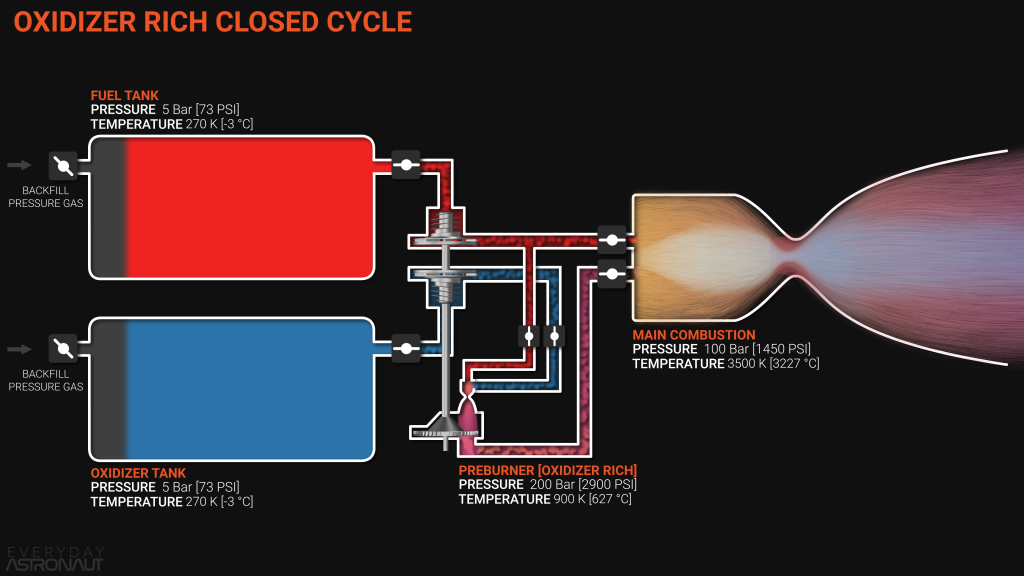
The Soviets chose to go down the oxygen-rich route because otherwise, if running on hydrocarbon-based fuels such as RG-1 or RP-1, the problems of coking and soot build-up would rapidly cause problems as mentioned earlier. So, in the oxygen-rich route, all of the oxygen runs through the turbine and on into the main combustion chamber.
Alongside the oxygen, only the minimal amount of propellant passes into the preburner – just enough to spin the pumps fast enough to create sufficient pressure and heat. The output from the preburner will lose pressure as it passes over the turbine. The turbine converts heat energy into mechanical work, spinning the pumps.
Now, let us make an observation here. The gas after the pressure drops across the turbine then flows into the main combustion chamber. If we remember what we said earlier about pressure and flow, fluids will always naturally flow from a region of high pressure to a region of low pressure.
Preburner Pressure
This means that the pressure in the preburner must be significantly higher than that of the main combustion chamber. This is necessary to ensure that the pressure after the turbine, and then again after the injector, is still higher than the pressure in the combustion chamber, with some margin of safety.
A decent “rule of thumb” to work with is to have a pressure in the preburner that is twice that of the main combustion chamber, and a pressure at the back of the injector that is 20% higher than that in the main combustion chamber. However, different engines, designed by different engineers, will vary the exact ratios depending on maturity and complexity of the design, and confidence in reliability of the specific design.
This leads to the next question of how is it possible to obtain a pressure in the preburner that is so much higher than that in the main combustion chamber.
In the oxygen-rich staged combustion cycle, all of the oxidizer must be compressed up to the highest pressure in the engine (for propellants at least), i.e. significantly higher than that of the main combustion chamber.
But the same cannot be said for the fuel. The majority of the fuel flows directly into the combustion chamber, so it only ever needs to be compressed up to 20% higher pressure than that in the combustion chamber. However, a small amount of fuel will need to be compressed further in order to enter the preburner.
Pump Stages
In other words, there are stages to the fuel pump. Most of the fuel passes through the first stage which will take it up to sufficiently high pressure to flow into the combustion chamber. Meanwhile only the minimum amount needed for the preburner goes through another compression stage that increases the pressure high enough to flow into the preburner.
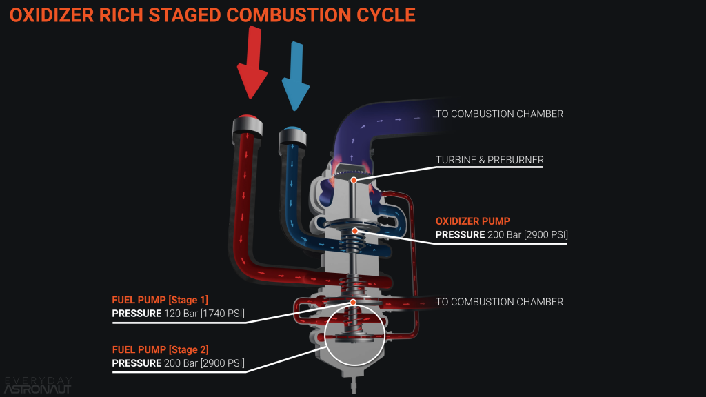
At this stage, you might wonder why, if the oxidizer has already been through the preburner, how can we burn it for a second time in the main combustion chamber? Remember that only a small amount of fuel goes into the preburner. Therefore only a small amount of oxidizer can have reacted with the fuel. Any remaining oxidizer leaves the preburner unburned. It has, however increased its temperature and changed from being in the liquid phase and is now in a gaseous phase.
The majority of the oxidizer has still not reacted with anything. So, it still retains all of its chemical energy when it enters the main combustion chamber, where it can then react with the fuel. This is where the main combustion takes place, unleashing the energy from the remaining un-reacted propellants.
Unfortunately the oxidizer-rich staged combustion cycle is extremely difficult to implement. This is the result of creating very hot gaseous oxygen. Such hot oxygen tends to react with almost everything in its environment. It requires very specific metal alloys that are capable of surviving such a hostile environment.
Oxygen-Rich Engine Cycle Examples
As previously mentioned, the Soviet engineers did master this cycle, as the majority of their engines used the oxidizer-rich staged combustion cycle, including the NK-15 and NK-33 for the N-1, the RD-170 on Energia, the RD-180 on the Atlas V, and the RD-276 on the Proton.
Also as previously mentioned, this was a very difficult technology to develop, and is something that the United States has not achieved for an orbital launch vehicle. This is not to say that the US abandoned the staged combustion cycle entirely, however.
Rather than attempting the oxidizer-rich cycle, they pursued the fuel-rich staged combustion cycle, for a specific engine that flew on an iconic vehicle. This is the RS-25 that flew on the Space Transportation System, better known as the Space Shuttle.
Fuel-Rich Staged Combustion Engine Cycle
Now let us consider the alternative to the oxygen-rich cycle, the fuel-rich cycle. In this case, where in general the relationship between the oxidizer and the fuel is reversed from what we looked at previously. In this case, all of the fuel passes through the preburner, and only a minimal amount of oxygen passes through the preburner.
If this were to be attempted on an engine running on long-chain hydrocarbons such as RP-1, then such an engine would suffer quickly from soot build-up and coking as discussed previously. However, it is possible to use fuels that are not carbon-rich. This is the approach taken originally by the United States.
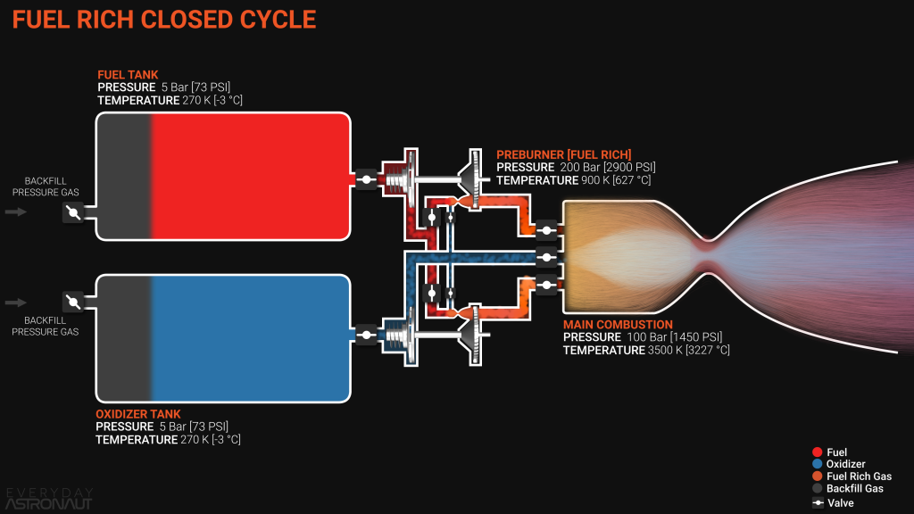
During the design of the main propulsion system for the Space Transportation System (or as mentioned earlier, better known as the Space Shuttle) the engineers opted for liquid hydrogen as the fuel, since they could run plain hydrogen fuel-rich through the preburner(s). Since hydrogen is such a light molecule and has zero carbon content, it does not lead to build-up of soot, and the engine is quite comfortable running on hot gaseous hydrogen.
This may appear to be an obvious solution, however fuel-rich staged combustion still has its own challenges – particularly when using hydrogen for fuel. This is because hydrogen is extremely light and volatile. It takes large pumps featuring multiple stages in order to achieve the high pressures that are needed.
One fairly common, and simple, mechanism for connecting pumps to the turbine is to have one shaft with the turbine on it and both pumps directly driven from it. This is fine if all three items can run at the same rotational speed.
Dual Preburners
Although single-shaft hydrolox fuel-rich closed cycle engines have been built, one example being the Soviet Union’s RD-0120 at the heart of the Energia booster, the USA chose a different solution for the Shuttle engines. This raised its own set of problems to overcome.
The design for the RS-25 featured dual preburners, each with its own shaft, and each being fuel-rich. One preburner powers the fuel pump stages and the other powers the oxygen pump.
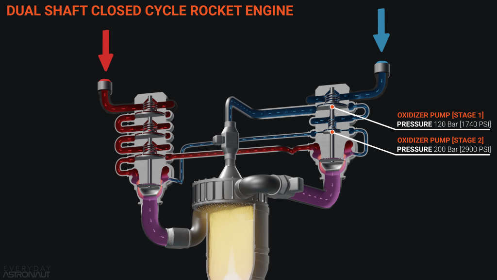
Unfortunately, having high-pressure hot gaseous hydrogen in a preburner that is on the same shaft as high-pressure liquid oxygen is a recipe for disaster. Should any of that hot gaseous fuel seep through the seals on the shaft and encounter the oxygen, it would be “game over” for the engine very quickly.
Purge Seals
This meant that the US engineers had to develop an extremely elaborate so-called purge seal. This prevents propellant traveling up or down the shaft by having an even higher pressure inert gas in the middle. Helium was chosen for this role. The purpose of this helium is to guarantee that in the event of any leak in a seal, the helium flows towards the propellant, and the propellants remain well separated.
The diagram below shows the two separate turbines, each with its own preburner, on a dual-shaft, fuel-rich closed cycle engine.
As you might expect, one preburner powers the oxidizer pumps and the other power the fuel pumps. Since both of the preburners are fuel-rich, all of the fuel will flow through one of the preburners and over the turbines before entering the main combustion chamber. Thus approximately half of the fuel flows through each preburner and turbine.
In the exact opposite to the oxidizer-rich closed cycle engine discussed earlier, only a minimal amount of oxidizer is fed through the preburners – just what is sufficient to extract enough combustion energy to spin the pumps. More specifically, to spin the pumps to the required speeds to drive the propellants through the preburners and into the combustion chamber.
Following the model discussed for the oxidizer-rich closed cycle, in this case most of the oxidizer flows through a single-stage pump that only needs to produce sufficient pressure to cause the oxidizer to flow into the main combustion chamber. Meanwhile, the small amount of oxidizer that is routed via the preburners then flows through a second stage of pumps in order to achieve the much higher pressures as discussed previously.
Fuel-Rich Engine Cycle Examples
The RS-25 was the first closed-cycle engine produced by the USA, however it was not the only fuel-rich engine to be developed. The Soviet Union also produced the RD-56 and RD-57 engines which were fuel-rich staged combustion hydrolox engines that were developed for a variant of the N1 moon rocket.
The Soviets also produced the RD-0120 mentioned earlier. This engine was at the heart of the Energia booster. It is to this day the most powerful single-chambered rocket engine that was ever flown by the Soviet Union.
So we have shown that the fuel-rich combustion cycle exchanges one set of complexities for another when compared with the oxygen-rich cycle. Before we move on, it is interesting to consider whether there is a good reason that methane fuel has not yet been used in a fuel-rich combustion cycle engine. We are unable to answer this question in this article.
There is one combustion cycle that combines the benefits of both fuel-rich and oxygen-rich cycles, which also combines some of the downsides of each of those – but one specific upside makes it well worth pursuing. Few organizations have attempted this however.
Full-Flow Staged Combustion Engine Cycle
The full-flow staged combustion cycle is named for the flow of the propellants through the preburners. Both the fuel and the oxidizer are totally routed through a preburner and a turbine. This means that the cycle design features both a fuel-rich preburner and an oxidizer-rich preburner.
The diagram illustrates the flow of the propellants as they are passed through the pumps and the turbines. Fuel and oxidizer both arrive at their respective pump inlets at tank pressure, then the pumps compress each of them up to full preburner pressures.
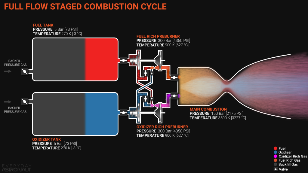
Almost all of the oxidizer is run through the oxidizer-rich preburner and turbine, with a minimal amount to oxidizer being sent through the fuel-rich preburner. In parallel, almost all of the fuel is run through the fuel-rich preburner and turbine, with a minimal amount of fuel being sent through the oxidizer-rich preburner.
This means that both propellants end up arriving at the combustion chamber already fully in gaseous form. This is a huge advantage over other cycles discussed earlier. A gas-gas interaction is extremely efficient, leads to improved mixing of gas products prior to combustion, leading to faster combustion with less unburnt residuals than liquid-liquid or liquid-gas interactions.
Or as Elon Musk told us:
Full-Flow Challenges
There is still the issue of having an oxidizer-rich staged combustion, meaning that there is hot gaseous oxygen to manage, as discussed for the oxidizer-rich cycle.
However, this problem is at least mitigated by being able to couple the oxidizer-rich turbine and shaft to the oxidizer pump, and also coupling the fuel-rich turbine and shaft to the fuel pump.
This avoids the problem mentioned for the fuel-rich cycle, i.e. there is no need for elaborate seal mechanisms to ensure that the fuel and the oxidizer remain well separated. This removes the need for rigorous inspection and maintenance between successive flights.
Perhaps the most significant advantage of full-flow staged combustion is not the benefit of the gas-gas interaction, or the comparatively simple seals involved, but the temperatures at which the preburners operate.
Enthalpy Considerations
Consider the equation shown below. We try to avoid equations in these articles in normal circumstances. However this may be useful to illustrate enthalpy that was discussed much earlier in this article.
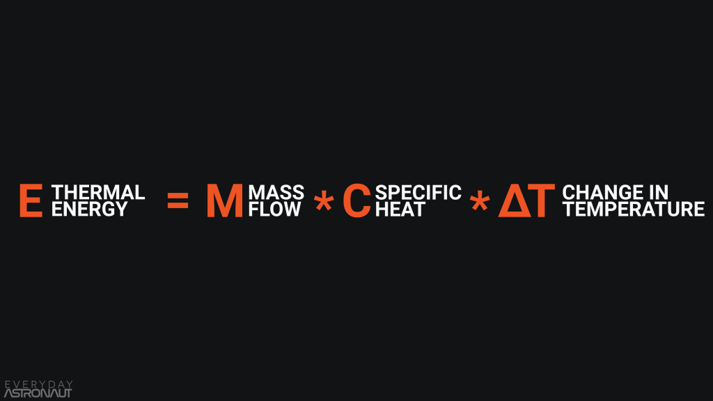
The higher the enthalpy, the more work that can be done. Unfortunately, higher enthalpy leads to higher temperatures. However, in the case of preburners, we have an amount of enthalpy needed to run the pumps that can be calculated.
Given a fixed thrust value and chamber pressure value, it is possible to obtain the amount of energy needed by the pumps to reach these values. In the equation above, the change in enthalpy is equal to the change in temperature multiplied by the specific heat, and then all of that divided by mass per second.
Since a full-flow engine and other closed-cycle engines will each require roughly the same amount of enthalpy to power the pumps, there is really only one other variable that changes between full-flow and the other cycles.
That variable is mass. Specifically the mass of the propellant flowing through the system, through the preburners to be precise. Since bother the fuel and oxidizer are all flowing through the preburners, this approximately doubles the mass flow compared with the other staged cycles.
Full-Flow Advantages
Now, in the enthalpy equation, if we double the mass flow, and there is no change to the required enthalpy, the changing variable is the temperature. Here is where the full-flow cycle has its greatest advantage.

All other things being equal, a full-flow engine will experience about half the temperature inside its preburners and therefore half the temperature across the turbine. This represents a “dream come true” for rocket engineers, since the heat load and its dissipation is often one of the biggest limitations for any engine.
Now, as attractive as the benefits of the full-flow cycle are to engineers, this cycle has often been considered not worth the effort due its perceived complexity. Since everything appears to be connected to everything else, any small change in one part of the engine can have a ripple effect across to everything else.
This results in the management of valve timings, startup and even throttling all being very difficult to master, and requiring a lot of investment to perfect. This is why so few full-flow engines have ever been developed.
Full-Flow Engine Cycle Examples
As usual, the Soviet Union was the first to develop a full-flow staged combustion cycle engine. This was the incredible RD-270. It ran on hypergolic propellants, and was enormous. It was only about 15% less powerful than the F-1 engine that powered the first stage of the Saturn V, and yet it was far more efficient.

Unfortunately, it never flew, as the massive UR-700 and UR-900 rockets for which it was designed were never given the green light to proceed.
The United States also developed the turbopumps for a full-flow staged combustion cycle engine in the 1990s. This was known as the Integrated Powerhead Demonstrator. Aerojet and Rocketdyne (now Aerojet-Rocketdyne) were successful in reaching the full capacity of the powerpack, however it was never developed into a full engine.
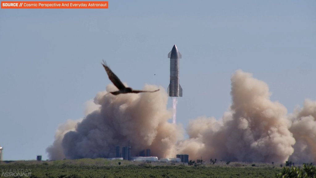
Today, SpaceX is now utilizing the full-flow staged combustion cycle on its Raptor engines that power the Starship upper stage and SuperHeavy booster.
All of this sounds very complicated. Suppose it was possible to dispose of the preburners entirely and have a simpler pump-fed engine? Well, there are two remaining cycles to discuss.
Tap-Off Engine Cycle
This next cycle may sound ridiculous, but let us consider punching a hole in the side of the main combustion chamber. This would lead to the escape of very hot, high-pressure gas. Could we direct this escaping gas in some way such that it could spin the turbine to run the pumps?
Well, this is the essence of what the tap-off or combustion tap-off rocket engine cycle is. The engine designers remove the complications and weight of either a preburner or a gas generator, and just use the main combustion pressure instead.
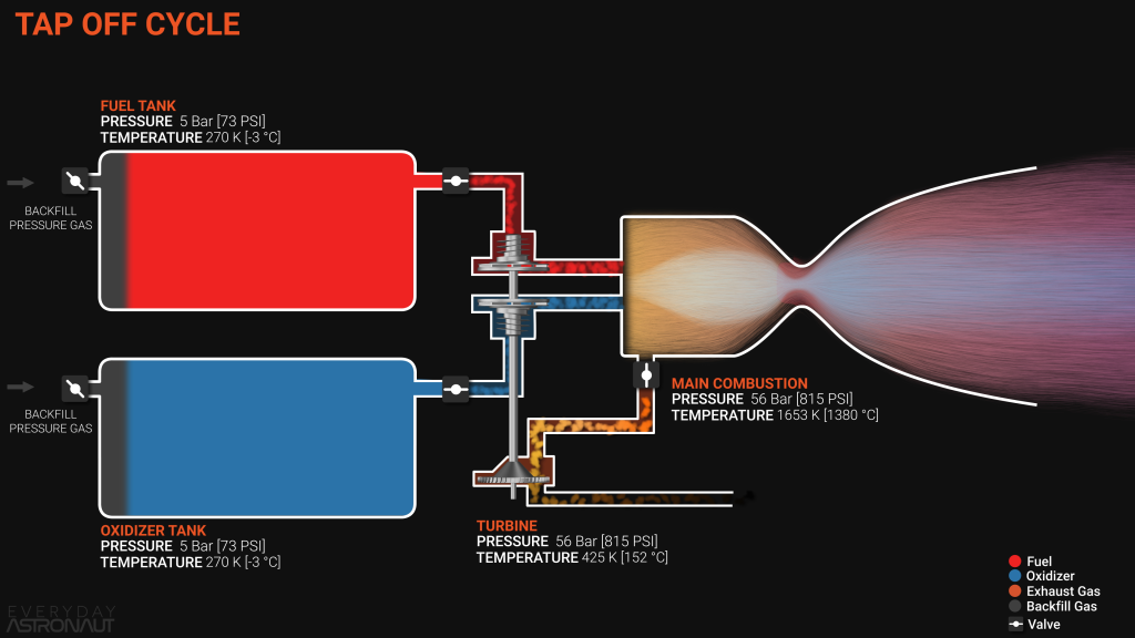
By having some gas products leave the combustion chamber from the side rather than from the nozzle, there is a small amount of performance loss. However its saves a lot of complexity which is an advantage.
An interesting aspect of the tap-off cycle is that it can be self-regulating to some extent, since it is possible to limit the amount of pressure that the turbine is exposed to with a choke, or by how much the throat leading to the turbine is reduced in diameter.
Tap-Off Engine Cycle Disadvantages
The disadvantage of this cycle is that the main combustion chamber gets extremely hot. The cycle design has no moving parts and usually uses regeneratively cooling, with fuel running through the walls. So the main combustion chamber can experience temperatures as high as 3500 K. This is far too hot for any turbine to withstand.
In order to get around this issue, engineers will sometimes arrange to dilute the tap-off gas before it reaches the turbine. They usually do this by adding in some fuel that helps to reduce the temperature by making the exhaust more fuel-rich. This is similar to how a typical gas generator functions.
After driving the turbine, the engine can either simply dump the exhaust overboard. Or it can reintroduce the exhaust into the nozzle at the most suitable point. This is where the pressure is both higher than the nozzle exit, and temperature is lower than the main combustion so it can film cool the chamber.
Tap-Off Cycle Examples
At the time of writing, no tap-off cycle engine has made it to orbit, but it has been used on multiple notable engines.
In the 1960s, NASA developed a follow-up to the J-2 engine used on the Saturn V 2nd and third stages. This was known as the “J-2, simplified”, or J-2S for short. As implied by the name, it was meant to be more simple and have higher performance by using the tap-off cycle.
This is a fully developed engine – that has never flown.
Today, Blue Origin utilizes the tap-off cycle on their BE-3 engine that powers their sub-orbital New Shepard rocket, and Firefly could be the first to reach orbit with their tap-off cycle Reaver and Lightning engines on their Alpha rocket.
However, there is one more system that has pumps but which does not require either a gas generator or a preburner, and this is the expander cycle.
Expander Engine Cycle
We already explained that heat is both a friend and an enemy in rocket engines. High temperatures can unlock new amounts of useful energy in a system, but they can also be damaging if they occur in the wrong place.
Now, there is one useful thing that an engine can do with its own heat, and that is to actually run the engine. Is this a form of recursion?
This is the description of the expander cycle. During the thermal expansion of the fuel or the oxidizer, energy is released. (The fuel is used most commonly.) The expander cycles harnesses this energy to cool the engine.
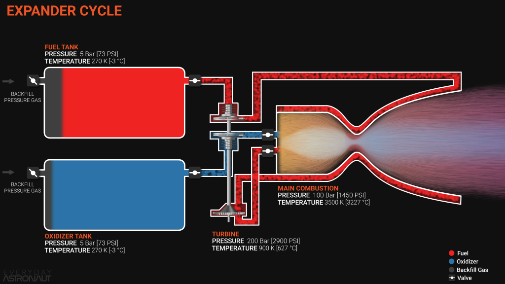
If you have seen the “why don’t rocket engines melt?” video or read the article, you may remember that a very common and extremely effective method of cooling a rocket engine is to pump the fuel through the walls of walls of the combustion chamber and nozzle to keep them cool.
In the process of cooling the walls, some of the heat from the combustion chamber passes to the fuel, so that the fuel absorbs some of that heat energy. Some fuels have better capacity for taking on such heat than others. Specifically, hydrogen is very good for this role due to its enormous heat capacity.
In all of the other engine cycles, they pump into the combustion chamber as a hot gas which then has to react with a liquid oxidizer. However, in the case of the expander cycle, we can take the heat energy removed by the fuel during regenerative cooling and use this to spin the turbine.
“Chicken vs. Egg” Problems
There approach has some problems. Firstly, we have another “chicken vs egg” situation. If the engine is not hot prior to ignition, how can it also power the pumps? This applies to several rocket engine cycles in this article.
It looks like we need a future video and article about how to start rocket engines. It is fairly common for engines to require a second energy source to get the pumps up to speed and then to get everything up to normal operating temperatures before they can run on their own in a self-sustaining manner.
Another problem with this cycle is that it has limited thrust output, based on the total amount of heat available in the system. To try to explain this, notice that as an engine grows in size, the amount of fuel flowing through the system also increases.
The increase in fuel flowing through the walls of the combustion chamber and nozzle increases the cooling capacity – and normally this is a good thing. The next observation is that when we increase the chamber size, the surface area of the walls goes up by the square of the chamber’s radius, whereas the volume goes up the radius cubed.
This means that it is easier to cool a large rocket engine than it is to cool a small engine. This is one of the main problems with aerospikes, as discussed in a previous video and article.
However, this same situation is what limits the amount of available energy that can spin the pumps. A larger engine requires more energy to spin the pumps, however this additional energy does not boil off the same percentage of fuel that flows through it, thus setting a limit on how powerful it can be.
Expander Cycle Limitations
In a similar way to the closed cycle engines, the pressure of the gaseous fuel has to be fairly high before it reaches the turbine. It has to be sufficiently high that it can go through the turbine (leading to a drop in pressure) and still have a healthy pressure margin over that in the main combustion chamber.
This means that the fuel pump has to do a lot of work to compress the fuel to these necessary pressures. In the case of liquid hydrogen, the pump will have to be huge, with several stages in order to obtain the required pressure.
In the case of a hydrogen-fueled engine with a single turbine, engineers may need to make use of a gearbox inside the turbopump so that they can arrange to direct the required speed and energy to the fuel pumps while sending less energy to the oxygen pump which does not need so much.
One again, we have a cycle that trades one form of simplicity and efficiency for a new complication and more moving parts. We can considered this as free energy available in the system in order to power the pumps. This is very efficient.
Some examples of engines using the expander cycle are the Vinci engine that will power the upper stage of the upcoming Ariane 6, the RL-10 engine that powers the upper stage of the Atlas V, and a variant that powers the Delta IV Heavy and will power the SLS upper stage.
Expander Cycle Variants
There is a variant of the expander engine cycle type, the expander bleed cycle. In this variant, the system is a little bit more simple due to avoiding returning the fuel to the combustion chamber after it has spun the turbine.
This means that more of the pressure can spin the pumps. Therefore the pressure after the turbine no longer needs to be higher than that in the combustion chamber. The engine only uses a small amount of the expanded hot gas to drive the pumps and then throws it overboard. So it wastes a small amount of unburnt fuel, but overall it is still very efficient.

This variant helps to overcome the limitations of available thrust since it is possible to use more of the limited pressure that is available to power the pumps. In other words, it trades a little bit of efficiency loss in exchange for the potential for increased thrust and lower complexity.
There are few examples of this variant, such as the BE-3U that will power the upper stage of Blue Origin’s upcoming New Glenn orbital rocket and the LE-5A and LE-5B on Japan’s H-I, H-II, and upcoming H-III rockets.
There is yet another variant on the expander cycle, known as the dual expander cycle. This utilizes both the fuel and the oxidizer to each run a set of pumps. This could be useful on some smaller engines that tend to run hot, such as for example future aerospike engines.
Summary
From the many rocket engine cycles available, there is no single “best” cycle type. Each system has its own particular method for powering a rocket engine. With each of these, there will inevitably be some trade-offs and compromises to consider.
Does it matter how high the performance of an engine is if that engine is unreliable in operation? On the other hand, pressure-fed engines are elegant and easy to use, but have limited performance.
In the meantime, the electric pump-fed cycle is finding more widespread usage as the energy density of lithium-based batteries increases due to advances in materials science.
The gas generator cycle is still one of the most common types. It has an effective compromise between performance and relative simplicity.
Closed cycle types have always been much sought after, and the Soviet Union’s engineers made this look easy. We should expect gains in performance compared with open cycle engines – at the cost of extra complexity.
Full-flow staged combustion is the most complex system here, however it does have the potential to lead to the coolest turbines and hottest combustion chamber. This can reach enormous levels of pressure and thrust safely.
It is surprising that there have not been more developments of the tap-off cycle. Once again it is relatively simple and reliable yet still be capable of high performance.
The expander cycle is also a very viable option, and it has proven to be great choice for the RL-10 engine. However it has limitations on levels of thrust output and as a result it is unlikely to see much use on a sea-level engine.
In the future we will look at more exotic engine types, such as ion propulsion or nuclear engines. For now, we hope you enjoyed this discussion on rocket engine cycles.
Thank you, well done.
This is an excellent description and well illustrated. I have a friend who likes to talk about details of space engineering, and this at least made me understand the basics. The only thing I found missing was mentioning what years the various kinds of cycles were put to use, for those of us who don’t know their rockets by heart.
Do you have a sources document for this information? I want to use it for a research paper.
Most of the times the source would be a conversation with actual engineers that have worked on the different types of engine cycles. I’ll see what I can find in terms of “paper” sources. Do you think citing our article wouldn’t work as a source?
Hey Tim. Could you point me to the video “Elon Musk Explains SpaceX’s Raptor Engine”, as cited in your video?
Cheers!
I think a fuel rich cycle methane engine would also run into some soot (or other incomplete combustion junk) problems. Though I think it should be much less of a problem than with RP-1 (with kerosene’s long chain hydrocarbons). Other than the pure carbon soot, with a preliminary search I find that you get methanol, formaldehyde, formic acid too (royalsocietypublishing.org/doi/pdf/10.1098/rspa.1939.0019) (though that was at low temperature of 300-450 C)
No idea what bearing all that has on feasibility of fuel right methane engines though. Better to talk less and test more!
Incomplete combustion is inevitable in any fuel rich mixture. The article you cite (thanks for the link) is primarily concerned with pre-ignition oxidation and the incomplete products mentioned are all flammable or break down in air.
tandfonline has a study specifically about soot formation from methane rich combustion:
https://www.tandfonline.com/doi/pdf/10.1080/00102202.2020.1787394
I didn’t realize that methane could produce much soot but it seems to require highly fuel-rich combustion to occur and I don’t have any real-world experience with that. If I’m reading it right then a fuel-rich staged combustor would be vulnerable as might fuel rich film cooling, but an oxygen rich combustor would not.
I think this article covers relevant topics, however there are many instances where an explanation is not made clearly. I believe the author should re-read this article and find the many places where the wording is not clear or where he should use a few more words/sentences to give a clear description of the technology.
i am from sri lanka and first thanks for this detailed and organized article, it is very good one. and i am currently writing a book regarding rocket technology, in sinhala language for the student and space enthusiastic in sri lanka. hope its fine to refer to ur article to get the details. and request the permission from u, this is due to plagiarism and believe its good ethics to get a permission from author. thank
Hey great video/article, but one question. So there was a MASSIVE orbital rocket designed called the Sea Dragon that would use 1 massive pressure fed engine to get to space, based one the info here that design would have been very inefficient of physically impossible?
Wonderful article! Love the detailed, simple explanations. I did notice some typos if you’ll forgive a humble fan’s attempt to improve readability. Under “Cold Gas Thruster Pressure”, third paragraph, second sentence “the” is written twice in a row rather than once. Under “Pressure Fed Engines”, first paragraph, third sentence “the offer much” is written instead of “THEY offer much”. Under “Bipropellant Pressure Fed Engines”, second paragraph, third sentence should “those engines” actually be “THESE engines”? Under “Oxygen-Rich Staged Combustion Engine Cycle”, second paragraph, second sentence “The achieved” should be “THEY achieved”. Under “Enthalpy Considerations”, fifth paragraph, third sentence “Since bother” should be “Since BOTH”. Under “Tap-Off Engine Cycle”, third paragraph, second sentence “However its” should be “However IT”. Under “Tap-Off Engine Cycle Disadvantages”, first paragraph, second sentence “regeneratively cooling” should be “REGENERATIVE cooling”. Under “Tap-Off Cycle Examples”, second paragraph, first sentence “2nd and third” should probably be “second and third” or have both as numbers with superscripts. Under “Expander Engine Cycle”, fourth paragraph “the walls of walls of” should be just “the walls of”. Under “Chicken vs. Egg Problems” first paragraph, first sentence “There” should be “Their”, and in the fourth paragraph, second sentence “goes up the radius cubed” should be “goes up BY the radius cubed”. Under “Expander Cycle Limitations”, fourth paragraph, first sentence “One” should be “Once”.
Again, I suggest these not as a criticism of content or the authors, but simply to refine content provided by an organization whose mission I admire.
Hey Tim! Excelent article.
I try to look into the future, what is coming after these traditional, already well-known techniques. What does the future of the RDE engine look like and how does it fit into this environment. are you doing an article on this potentially promising technology. What are its real challenges and promises at the moment?
isn’t the engine on delta IV rs-68 instead of rd-68 in the article