


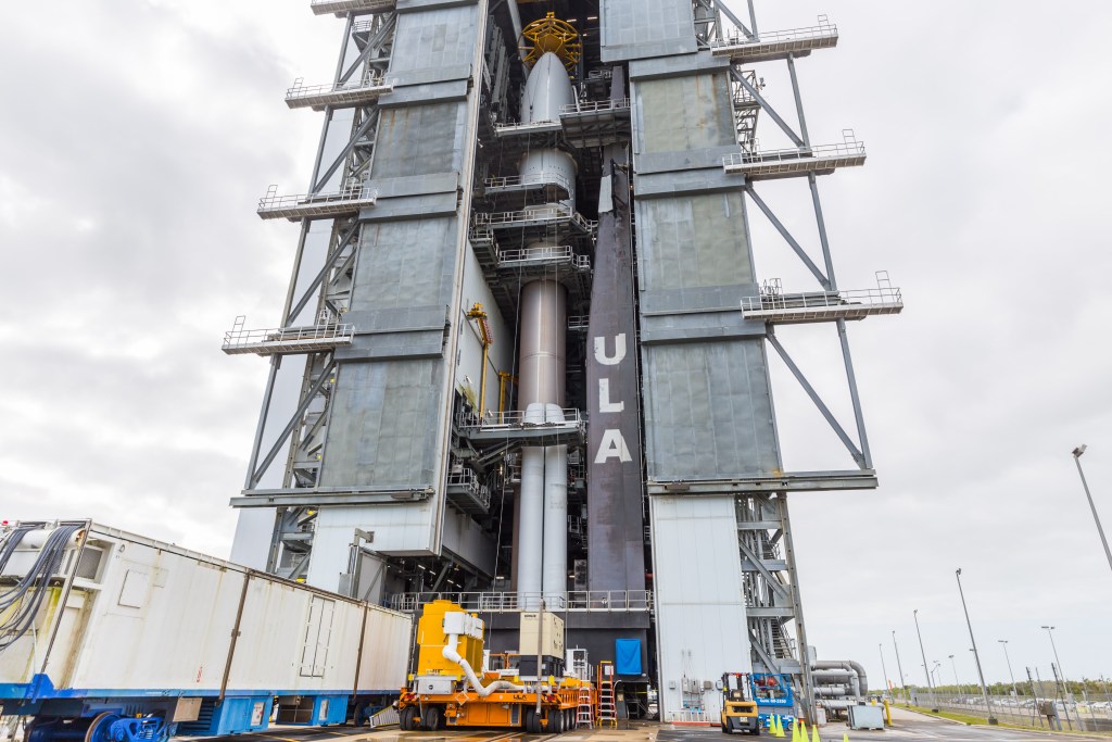
Featured image credit: ULA
Lift Off Time | March 01, 2022 – 21:38 UTC | 16:38 EST |
|---|---|
Mission Name | GOES-T, NOAA’s next generation weather satellite |
Launch Provider | United Launch Alliance (ULA) |
Customer | National Aeronautics and Space Administration (NASA), National Oceanic and Atmospheric Administration (NOAA) |
Rocket | Atlas V 541 |
Launch Location | SLC-41, Cape Canaveral SFS, Florida, United States |
Payload mass | 5,192 kg (~11,400 lb) |
Where are the satellites going? | Geostationary transfer orbit (GTO) |
Will they be attempting to recover the first stage? | No, Atlas V is not capable of recovery |
Where will the first stage land? | It will crash into the Atlantic Ocean |
Will they be attempting to recover the fairings? | No, Atlas V is not capable of recovery |
Are these fairings new? | Yes |
How’s the weather looking? | The weather is currently 80% GO for launch (as of March 01, 2022 – 13:00 UTC) |
This will be the: | – 8th flight of the Atlas V 541 configuration – 2nd launch of ULA in 2022 – 76th Atlas V launch from Cape Canaveral – 149th ULA’s mission – 22nd orbital launch attempt of 2022 |
Where to watch | NASA’s Official livestream |
What Does All This Mean?
United Launch Alliance (ULA) is launching NASA’s and NOAA’s GOES-T next generation weather satellite. This mission will see the use of an Atlas V 541 launching from Space Launch Complex 41 at Cape Canaveral Space Force Station in Florida, USA. The Geostationary Operational Environmental Satellite (GOES) -T is NOAA’s next generation weather satellite following the two satellites GOES-R and GOES-S. The satellite will be inserted into a highly elliptical geostationary transfer orbit. This mission will mark ULA’s second launch in 2022, with USSF-8 being the first one back in January of 2022.

GOES-T
GOES-T is NOAA’s fourth generation weather satellite. Following the satellites GOES-R and GOES-S, GOES-T will be the third satellite of the GOES-R series of satellites. Following NOAA’s third generation GOES satellites, launched until 2010, this fourth generation brings many upgrades to further improve weather monitoring and forecasting capabilities. As is standard with all GOES satellites, GOES-T will be renamed to GOES-18 as soon as it reaches its final orbit, which will be at the GOES-West position at 137° W, replacing the faulty GOES-17.
GOES-17 experienced an anomaly when its onboard loop heat pipe (LHP) wasn’t able to sufficiently cool the satellite’s Advanced Baseline Imager (ABI) to ensure constant operation of the instrument. This reduced the instrument’s imaging capability of 13 infrared and near-infrared channels to only 12 hours per day. GOES-T will replace GOES-17, which will stay in orbit as an on-orbit back up to GOES-T.
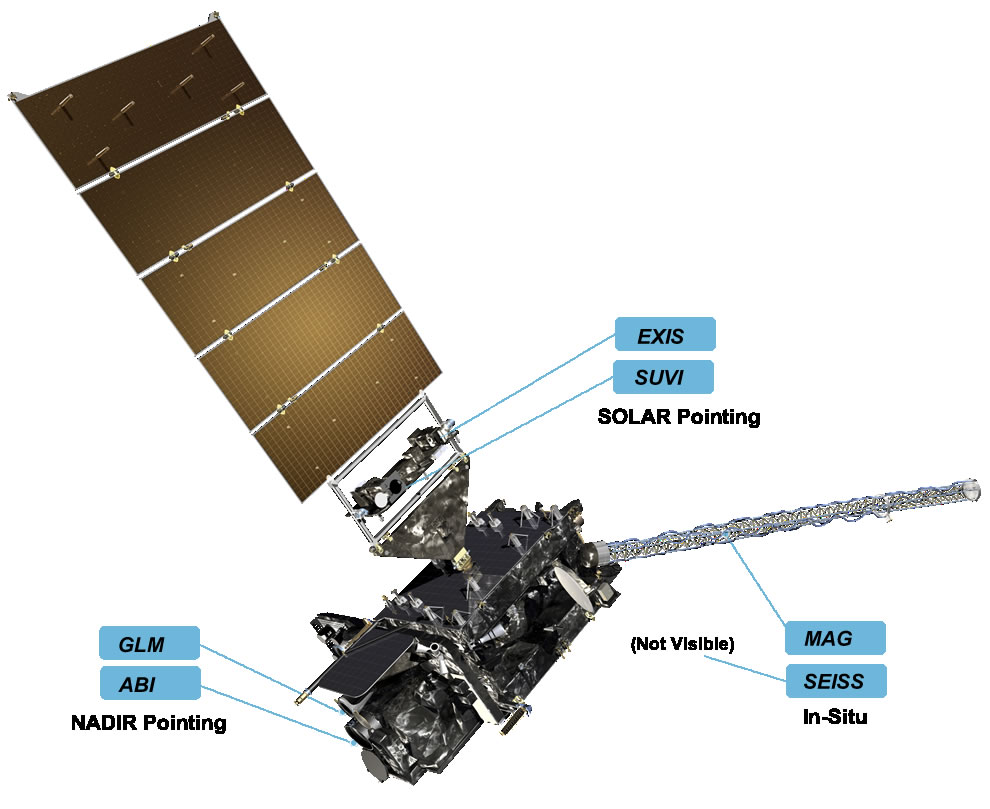
GOES-T Instruments
GOES-T features six major instruments that can be divided into three groups.
- NADIR-pointing:
- Advanced Baseline Imager (ABI)
- Geostationary Lightning Mapper (GLM)
- Solar-pointing:
- Extreme Ultraviolet and X-ray Irradiance Sensors (EXIS)
- Solar Ultraviolet Imager (SUVI)
- In-Situ:
- Space Environment In-Situ Suite (SEISS)
- Magnetometer (MAG)
Advanced Baseline Imager (ABI)
The ABI is GOES-T’s primary instrument and views Earth in 16 different spectral bands, whereas the previous generation only observed Earth in five spectral bands. The 16 channels are comprised of two visible channels, four near-infrared ones and ten infrared channels. The different channels correspond to different wavelengths, making it possible to observe features on Earth’s surface, or in the amosphere. The ABI will be responsible for 65% of all data gathered by GOES-T and has four major imaging modes:
- Full Disk: Hemispheric coverage of 83° local zenitz angle, every 5-15 minutes, with a resolution of 0.5 to 2 km.
- Mesoscale: 1,000 km x 1,000 km square every 30 seconds, with a resolution of 0.5 to 2 km.
- Continental US/Pacific US: 5,000 km x 3,000 km CONUS and PACUS scans every five minutes, with a resolution of 0.5 to 2 km.
- Flex Modes: multiple variations of the modes above with the same 0.5 to 2 km resolution.
| Attribute | ABI | 3rd Generation Imager |
|---|---|---|
| Spectral Coverage | 16 bands | 5 bands |
| Spatial Resolution: | ||
| 0.64 µm Visible | 0.5 km | ~1 km |
| Other Visible/Near-IR | 1.0 km | n/a |
| Bands (>2 µm) | 2 km | ~4 km |
| Spatial Coverage: | ||
| Full Disk | 6 per hour | Scheduled (3 hrly) |
| CONUS | 12 per hour | ~4 per hour |
| Mesoscale | 30 or 60 seconds | n/a |
| Visible (reflective bands): | ||
| On-Orbit Calibration | Yes | No |
Geostationary Lightning Mapper (GLM)
The GLM is is a single-channel, near-infrared detector that detects momentary changes in the observed scene caused by lightning, with its 2 ms frame rate. The GLM can measure lightning types, such as in-cloud, cloud-to-cloud, and cloud-to-ground all over the Americas and the adjacent ocean regions. The detector has a resolution of around 10 km and collects information like frequency, location, and extent of lightning discharges. This data is used identify intensifying thunderstorms and tropical cyclones and can help increase lead time for thunderstorm and tornado warnings.
Extreme Ultraviolet and X-ray Irradiance Sensors (EXIS)
The EXIS instrument is composed of two main sensors, the Extreme Ultraviolet Sensor (EUVS), and the X-Ray Sensor (XRS). The EXIS instrument is located on the Sun-Pointing Platform (SPP) and will therefore face the Sun. Both sensors are pointed at the Sun to monitor its activity. While the XRS will monitor solar flares to help predict solar proton events that have the potential of penetrating Earth’s magnetic field, the EUVS measures changes in the solar extreme ultraviolet irradiance, which can affect Earth’s upper athmosphere in a way that drag on satellites in low-Earth orbit can increase. Both, extreme ultraviolet irradiance and solar flares have the potential to cause radio blackouts.
Solar Ultraviolet Imager (SUVI)
The SUVI is a telescope that is pointed at the sun and captures it in the extreme ultraviolet wavelength range. SUVI will capture full disk images of the Sun and will monitor solar eruptions, to identify their trajectory and intensity, as eruptions like this can cause geomagnetic storms that have the potential to disrupt power utilities, communication, and navigation systems. They can also cause radiation damage to satellites and the ISS. SUVI will provide information on coronal plasma temperatures and emission measurements that will help improve space weather forecasting.
Space Environment In-Situ Suite (SEISS)
SEISS consists of four separate instruments that monitor proton, electron, and heavy ion fluxes in Earth’s magnetosphere. The four instruments are:
- Energetic Heavy Ion Sensor (EHIS)
- Magnetospheric Particle Sensors – High and Low (MPS-HI/MPS-LO)
- Solar and Galactic Proton Sensor (SGPS)
Data retrieved by those sensors will not only help with hazard assessment, but also with warning from high flux events that can damage radio communication. Parts of NOAA’s space weather scales are supplied with data from those sensors, which will improve energetic particle forecasts. SEISS also houses the Data Processing Unit (DPU).
Magnetometer (MAG)
The Magnetometer, used on every GOES satellite since the start of the program, provides crucial data about the environment around the satellite. MAG provides information about the Earth’s magnetic field and the charged particles that sit within. The information is critical, as higher amounts of charged particles and radiation can cause harm to spacecraft and humans living in space.
Since GOES-T will be placed in a geostationary orbit, the GOES-R magnetometer will be one of the first to deliver data about fluctuations or changes in the Earth’s magnetic field. GOES-T can then send the data to other satellite operators and advise them to take necessary action.
GOES-T Mission Timeline
| Hrs:Min:Sec | Events |
| -0:00:02.7 | RD-180 engine ignition |
| +0:00:01.0 | Liftoff |
| +0:00:05.3 | Begin pitch/yaw maneuver |
| +0:00:35.3 | Mach 1 |
| +0:00:48.0 | Maximum dynamic pressure |
| +0:01:50.7 | Solid rocket booster jettison |
| +0:03:30.2 | Payload fairing jettison |
| +0:04:22.8 | Atlas booster engine cutoff (BECO) |
| +0:04:28.8 | Atlas Centaur separation |
| +0:04:38.7 | Centaur first main engine start (MES-1) |
| +0:12:05.6 | Centaur first main engine cutoff (MECO-1) |
| +0:23:39.1 | Centaur second main engine start (MES-2) |
| +0:28:14.3 | Centaur second main engine cutoff (MECO-2) |
| +3:28:28.4 | Centaur third main engine start (MES-3) |
| +3:30:07.3 | Centaur third main engine cutoff (MECO-3) |
| +3:32:56.3 | GOES-T separation |
| +3:59:16.3 | Start blowdown |
| +4:32:36.3 | End of mission |
What Is The Atlas V?
The Atlas V is an expendable medium-lift launch system and member of the Atlas rocket family. The rocket has two stages. The first is a Common Core Booster (CCB), which is powered by a single RD-180 engine that burns kerosene (RP-1) and liquid oxygen (LOx). This is accompanied by up to five strap-on solid rocket boosters (SRB). The second stage is the Centaur upper stage, which is powered by one or two RL10 engines and burns liquid hydrogen (LH2) and liquid oxygen (LOx).
The CCB is 3.8 m (12.5 ft) in diameter and 32.5 m (106.5 ft) in length. This stage is capable of producing 3.83 MN (860,200 lb) of thrust at sea level. Each SRB can provide additional 1.6 MN (371,550 lb) of thrust. The Centaur second stage, in turn, is 3 m (10 ft) in diameter and 12.6 m (41.5 ft) in length and is capable of producing 101.8 kN (22,900 lb) of thrust.
What Does 541 Mean?
Atlas V rockets have a three number configuration code. The first number represents the fairing diameter size in meters. The second number denotes the number of solid rocket motors (SRMs), which attach to the base of the rocket. The number of SRMs for a 4 meter fairing can range from 0 – 3. However, the 5-meter fairing Atlas V can support up to 5 SRMs, due to the different aerodynamic properties of the fairing. For the GOES-T mission, there will be four SRM attached to the center core. The third number denotes the number of engines on the Centaur Upper Stage.
