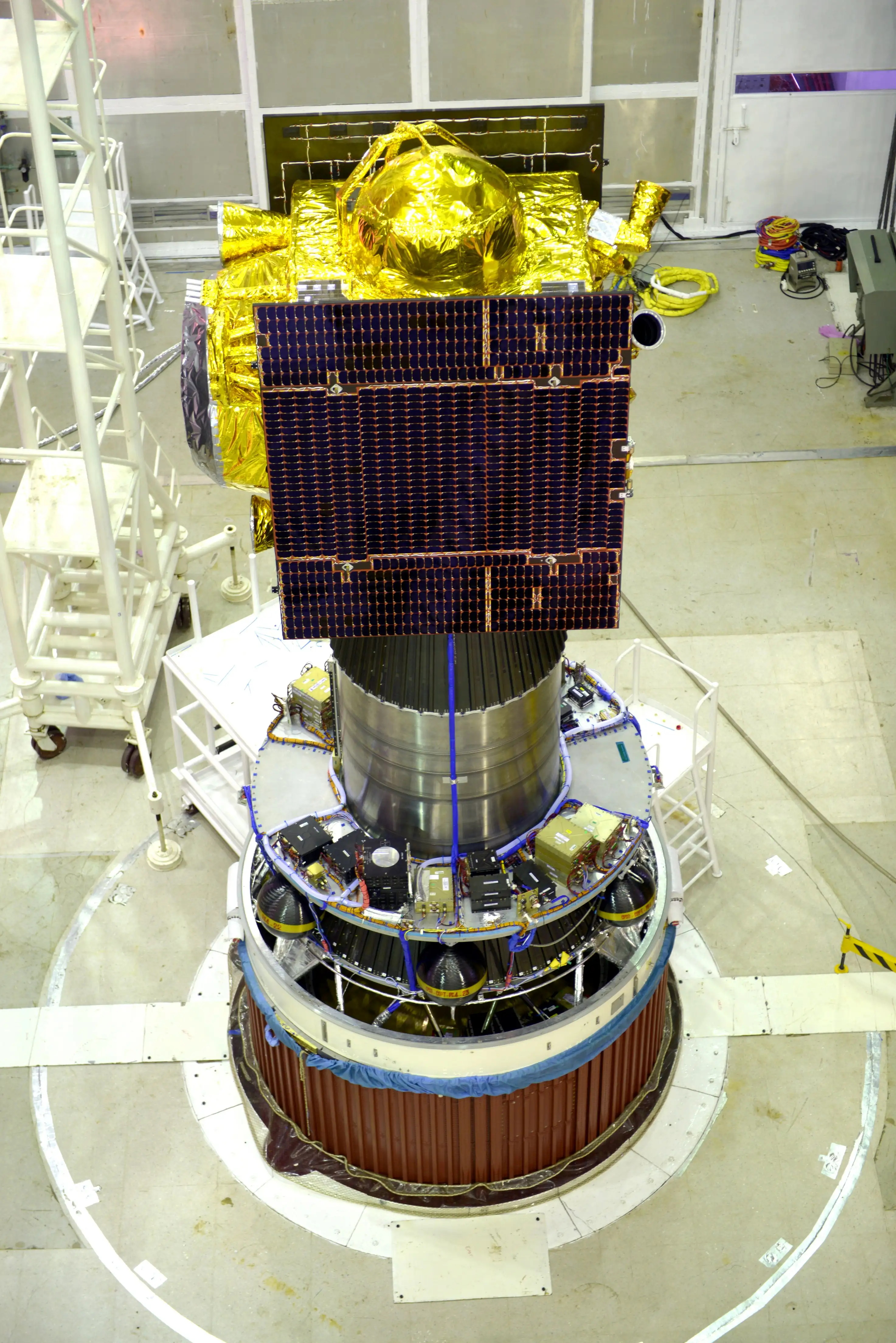
Featured image’s credit: ISRO
Liftoff Time | September 2, 2023 – 06:20 UTC | 11:50 IST |
|---|---|
Mission Name | Aditya-L1 |
Launch Provider | The Indian Space Research Organization (ISRO) |
Customer | The Indian Space Research Organization (ISRO) |
Rocket | Polar Satellite Launch Vehicle, or PSLV-XL (PSLV-C57) |
Launch Location | First Launch Pad (FLP) located at the Satish Dhawan Space Centre, on the Sriharikota island, India |
Payload mass | 1,480.7 kg (~3,260 lb) |
Where did the spacecraft go? | Halo orbit around the Lagrange point number one in the Sun-Earth system (Sun-Earth L1); initially, 235×19,500 km (146×12,120 mi) x 19.2° |
Did they attempt to recover the first stage? | No. The PSLV rocket does not have this capability |
Where did the first stage land? | It crashed into the Bay of Bengal |
Did they attempt to recover the fairings? | No. The PSLV rocket does not have this capability |
Were these fairings new? | Yes |
This was the: | – 138th orbital launch attempt in 2023 – 3rd PSLV mission in 2023 – 59th PSLV mission overall – 7th ISRO mission in 2023 – 91st ISRO mission overall |
Where to watch | Official replay |
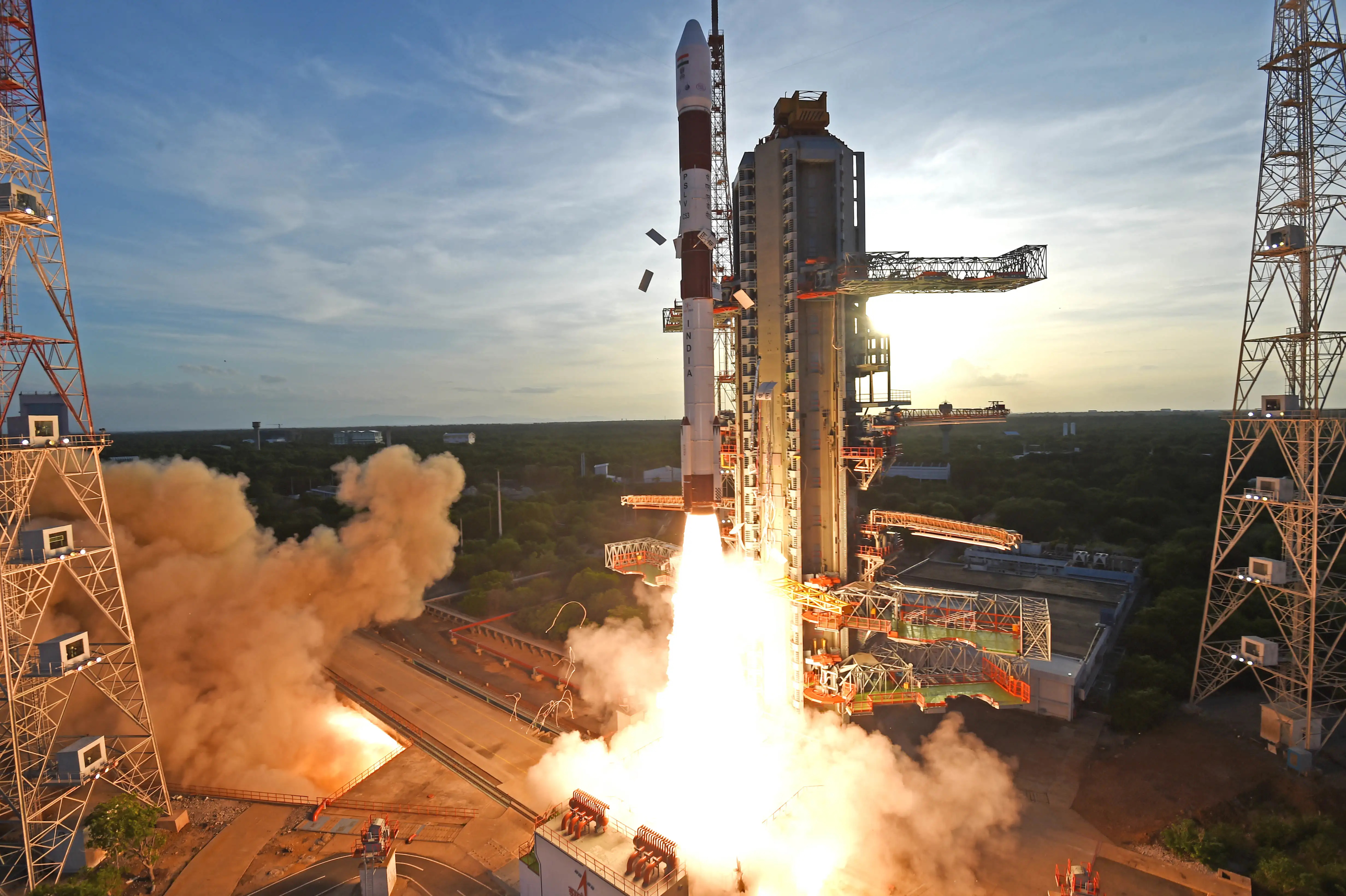
How Did It Go?
The Indian Space Research Organization (ISRO) successfully launched its first solar observatory, Aditya-L1, on a PSLV-XL rocket. Additionally, this was the first payload the agency has sent to the Lagrange point one in the Sun-Earth system (Sun-Earth L1). In order to carry out this mission, the launch vehicle lifted off from Sriharikota Island. Specifically, it left from the First Launch Pad at the Satish Dhawan Space Centre, Sriharikota, India. After the launcher finished its task, the spacecraft entered a highly elliptical Earth orbit, from where it will increase its orbit. Aditya-L1 will use its own propulsion system to travel for ~110 days to the previously mentioned L1 point.
What Is Aditya-L1?

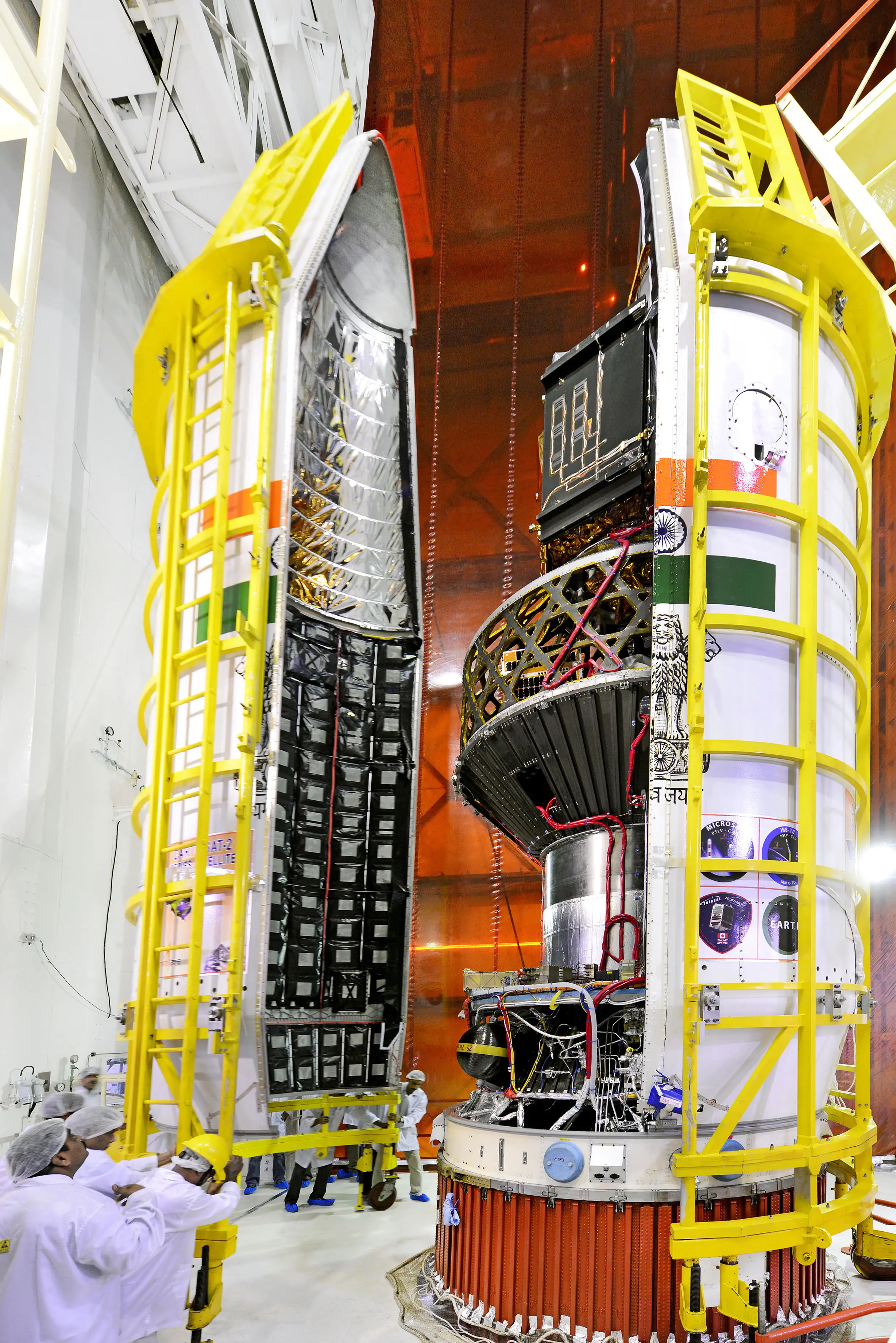
Aditya is the name of the Sun in Sanskrit, and, with this in mind, ISRO has built a spacecraft carrying a series of instruments or payloads. Aditya-L1, therefore, comes into being for studying the Sun and its influence on our solar system. More specifically, the U R Rao Satellite Centre (URSC), was responsible for its development and manufacturing. Further institutions or centers joined the work, providing different components, e.g., some of the seven scientific instruments. Having such a variety of devices intended for science certainly makes of Aditya-L1 a solar observatory in its own right.
However, the spacecraft requires other resources to be able to accomplish its mission’s objectives, which should extend for at least five years. On one hand, Aditya-L1 needs a propulsion system to arrive at its intended destination. It will also necessitate adequate thermal management, among other onboard subsystems.
On the other hand, teams back on Earth will be in charge of performing scientific tasks leveraging the data collected in orbit. In order to do that, communications should be fluid between the observatory and the ground. In particular, the European Space Agency (ESA) will support said exchange of information.

Instruments On Aditya-L1
Through its suite of instruments, Aditya-L1 will enable scientists to address a wide spectrum of problems in solar physics. The following subsections describe their most important aspects.

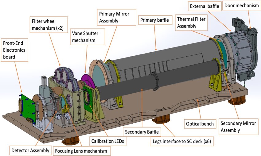
Visible Emission Line Coronagraph (VELC)
The Indian Institute of Astrophysics, in Bangalore, developed this instrument, which is the main payload aboard Aditya-L1. VELC will study parameters that are critical to the dynamics of both the corona and coronal mass ejections (CME). In order to do so, the coronagraph makes use of the internal occultation technique. That is, it blocks the light coming from the disk of the Sun. Hence, fainter phenomena in its outer regions become more easily observable.
Four different mirrors reflect the incoming light, while making it travel through a collimating lens and polarization filters. The former directs the light rays so that they are parallel to one another, eliminating optical distortion and aberration. The latter provide a means of observing the direction in which light oscillates, giving information about coronal magnetic fields. Finally, two dichroic beam splitters and two steering mirrors let the light beams arrive into three sensors.

Two of them measure light emitted in specific frequencies in the visible spectrum, whereas a third performs broader imaging around another such frequency. Furthermore, VELC operates in four possible modes, focusing on intensity oscillation, loop dynamics, magnetic topology, and CME studies. In addition to all of the data the observatory will gather, ground-based telescope measurements will aid in analyzing the magnetic coupling from the photosphere to the corona.
Solar Ultra-violet Imaging Telescope (SUIT)
In this case, the Inter University Centre for Astronomy & Astrophysics, in Pune, is the entity that conceived SUIT. Taking images of both the photosphere and the chromosphere in near ultra-violet, with great spatial resolution, this instrument will monitor solar irradiance. That is, how much energy the Sun is emitting from different points on it.
Furthermore, ground-based telescope measurements will supplement the information, delivering vital magnetic field data. Concurrently, SUIT will offer uninterrupted observations spanning the photosphere, chromosphere, and lower transition region of the Sun.
Aditya Solar wind Particle EXperiment (ASPEX)
In Ahmedabad, the Physical Research Laboratory developed ASPEX, with the goal of studying the solar wind. Measuring its properties, e.g. composition, temperature, velocity, among others, it is possible to learn about its origin, behavior, and interaction with the solar system. Additionally, it will also determine when CMEs arrive at the Sun-Earth L1. This will complement coronal observations.
In order to do all of that, it implements two separate instruments:
- SWIS (Solar Wind Ion Spectrometer): it identifies types of particles, as well as measures their angular and energy distributions.
- STEPS (Supra Thermal Energetic Particle Spectrometer): it samples the solar wind along four directions studying particles with higher-than-average energy.
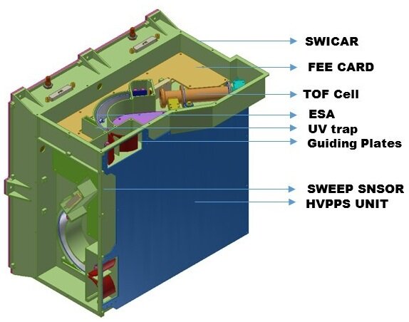
Plasma Analyzer Package for Aditya (PAPA)
The Vikram Sarabhai Space Centre, located at Thiruvananthapuram, had its Space Physics Laboratory dedicated to developing PAPA. Aditya-L1 will use it to measure electron distribution in both the solar wind and the interplanetary medium. In turn, this will allow it to determine solar wind composition and energy distribution.
To this end, it will make use of the instruments:
- SWEEP (Solar Wind Electron Energy Probe)
- SWICAR (Solar Wind Ion Composition Analyzer)
Solar Low Energy X-ray Spectrometer (SoLEX)

This instrument, developed by the U R Rao Satellite Centre, in Bangalore, aims at studying X-ray flares in a certain energy range (1 to 30 keV, or kiloelectron-Volts). Moreover, it will probe the connection between these flares and CMEs. In further detail, SoLEXS will measure:
- Coronal temperature,
- Differential emissions (basically, the Sun’s thermal structure), and,
- Plasma abundances (related to the elemental composition of the Sun’s atmosphere).
High Energy L1 Orbiting X-ray Spectrometer (HEL1OS)
Also developed by the U R Rao Satellite Centre, in Bangalore, HEL1OS treats the Sun as a distant star. In this way, its observations in the hard X-ray spectrum allow it to study flares in their impulsive phase. That is, the very bright phenomenon in the solar atmosphere, where charged particles are accelerated with great energy. Thanks to these measurements, scientists could gain insight regarding the mechanism behind flares.
Two kinds of semiconductors will detect thermal, as well as non-thermal components of flares. On the other hand, measurements from VELC, SoLEXS, SUIT, and ground-based radio observations will complement those this instrument will perform.
Magnetometer

These are two sensors mounted on a boom that is 6 m (~20 ft) long, both of them ring core based with ferromagnetic material. They have been developed by the Laboratory for Electro Optics Systems, in Bangalore. Their installation away from the spacecraft should ensure Aditya-L1’s own fields will not alter their measurements.
Sensitive to constant and variable magnetic fields, the magnetometers’ task is to determine the dynamic variations in the interplanetary ones. Equally important is comprehending extreme solar events, like CMEs, and how all of this impacts on Earth’s space environment.
Science by Aditya-L1
The solar observatory is set to do research related to the Sun’s properties, uncovering the dynamics and origins of coronal mass ejections while observing real-time solar activities and their space weather impact. The seven payloads carried on the spacecraft enable observations of the photosphere, chromosphere, and the outermost solar layers — the corona — through electromagnetic, particle, and magnetic field detectors.
While four payloads provide a direct view of the Sun, the remaining three focus on in-situ studies of particles and fields at L1. These investigations offer essential insights into solar dynamics’ effects extending throughout the interplanetary medium. Aditya’s payloads promise vital information for comprehending coronal heating, coronal mass ejections, pre-flare and flare activities, space weather dynamics, and the propagation patterns of particles and fields.
The following are summarizing notes to better grasp the mission’s goals and interesting facts.

Major Objectives
Uncovering of the mystery behind the Sun’s outer atmosphere heating process and the acceleration of solar wind.
Understanding of the beginning stages of events like coronal mass ejections, solar flares, and their impact on space weather closer to our planet.
Deciphering of how the different layers of the Sun’s atmosphere connect and change over time.
Analysis of the way solar wind spreads and how temperature variations play out in different directions in the Sun’s atmosphere.
Distinctive Mission Features
Seeing the Sun up close in UV: observing the solar disk in near UV for the first time.
Exploring solar eruptions: studying CME dynamics near the solar disk to uncover acceleration details not seen before.
Smart detection of solar events: equipped with onboard intelligence to spot CMEs and solar flares, optimizing data collection.
Unveiling solar wind secrets: investigating the solar wind’s direction and energy variations through observations from multiple angles.
Trajectory And Orbit
Aditya-L1’s first steps toward reaching orbit are in the following table, listing a summary of milestones for the PSLV’s flight.
| Event | Time [hh:mm:ss] | Altitude [km] | Inertial Velocity [m/s] |
|---|---|---|---|
| RCT Ignition | -00:00:03.00 | 0.025 | 451.9 |
| PS1 Ignition | 00:00:00.00 | 0.025 | 451.9 |
| PSOM XL 1, 2 (GL) Ignition | 00:00:00.42 | 0.025 | 451.9 |
| PSOM XL 3, 4 (GL) Ignition | 00:00:00.62 | 0.025 | 451.9 |
| PSOM XL 5, 6 (AL) Ignition | 00:00:25.00 | 2.725 | 625.9 |
| PSOM XL 1, 2 (GL) Separation | 00:01:09.90 | 24.196 | 1479.5 |
| PSOM XL 3, 4 (GL) Separation | 00:01:10.10 | 24.326 | 1484.5 |
| PSOM XL 5, 6 (AL) Separation | 00:01:32.00 | 40.558 | 2094.5 |
| PS1 Separation | 00:01:49.40 | 55.496 | 2407.3 |
| PS2 Ignition | 00:01:49.60 | 55.663 | 2406.8 |
| CLG Initiation | 00:01:54.60 | 59.745 | 2435.0 |
| PLF Separation | 00:03:24.40 | 113.220 | 3756.5 |
| PS2 Separation | 00:04:22.38 | 130.372 | 5400.7 |
| PS3 Ignition | 00:04:23.58 | 130.597 | 5400.3 |
| PS3 Separation | 00:09:41.42 | 192.868 | 7728.3 |
| PS4 Burn – 1 Ignition | 00:24:53.52 | 313.067 | 7587.5 |
| PS4 Burn – 1 Cut – off | 00:25:23.38 | 313.070 | 7677.8 |
| PS4 Burn – 2 Ignition | 00:52:07.52 | 217.614 | 7793.6 |
| PS4 Burn – 2 Cut – off | 00:59:59.52 | 342.650 | 9695.0 |
| Aditya – L1 Separation | 01:03:19.52 | 648.781 | 9429.2 |
| MON Passivation Start | 01:07:22.52 | 1232.269 | 8956.9 |
| MMH Passivation Start | 01:13:02.52 | 2298.785 | 8212.3 |

The solar observatory, Aditya-L1, will find itself in an orbit around the Earth right after deployment from the PSLV’s fourth stage. Such an orbit will be of about 235 km (~146 mi) by 19,500 km (~12,120 mi), which is quite elliptical. A series of burns will raise the spacecraft’s apogee, finally leaving our planet’s sphere of influence (SOI) after crossing the 918,300 km (~570,740 mi) mark in altitude.

A coasting phase will take place, until the proximity of Sun-Earth L1 demands an insertion burn. Once stationed at L1, the observatory will experience a nearly constant distance from the Sun and won’t be eclipsed by Earth, ensuring uninterrupted study of solar activities. Logically, Aditya-L1 will always be in line of view from the ground, favoring communications.
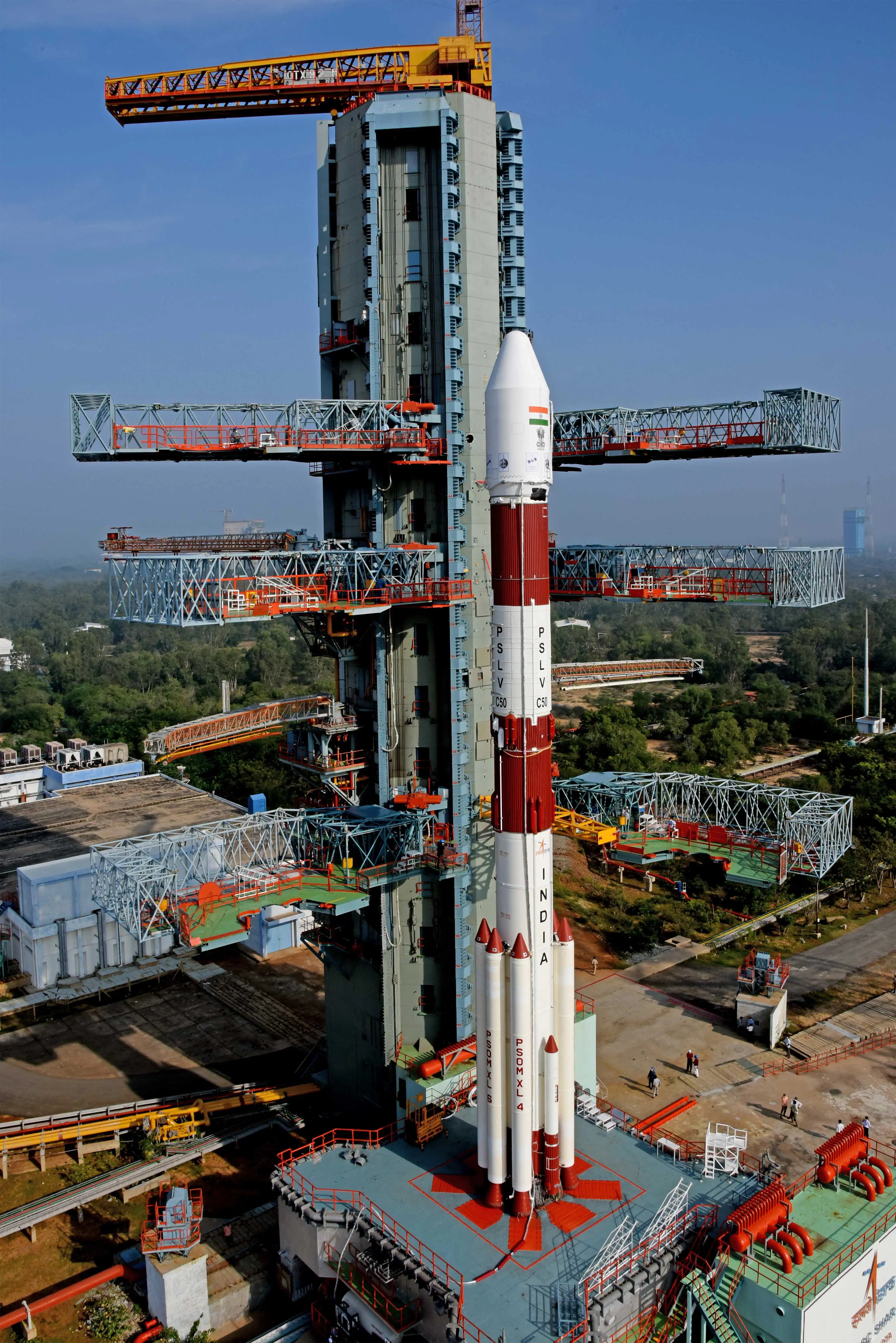
What Is The PSLV?
Originally conceived to launch into SSO, the Polar Satellite Launch Vehicle (PSLV) is, in short and according to ISRO, its workhorse. In essence, it is an expendable medium-lift launch vehicle developed and manufactured by the Indian agency. However, ISRO’s commercial arm, NewSpace India Limited (NSIL), has taken over this rocket’s production — at least partly — since 2019 in addition to providing launch services. Further, through NSIL the local industry and other institutions become a part of the process.
| Height [m (ft)] | 44.4 (~146) |
| Strap-on motors for variants CA, DL, QL, G/XL | 0, 2, 4, 6 |
| Liftoff mass(1) [kg (lb)] | 320,000 (~711,000) |
| Mass to LEO(2) [kg (lb)] | 3,800 (~8,400) |
| Mass to SSO(3) [kg (lb)] | 1,750 (~3,800) |
| Mass to sub-GTO(4) [kg (lb)] | 1,425 (~3,100) |
(2) 200 km (~120 mi).
(3) 600 km (~370 mi).
(4) 284×20,650 km (~176×12,800 mi).
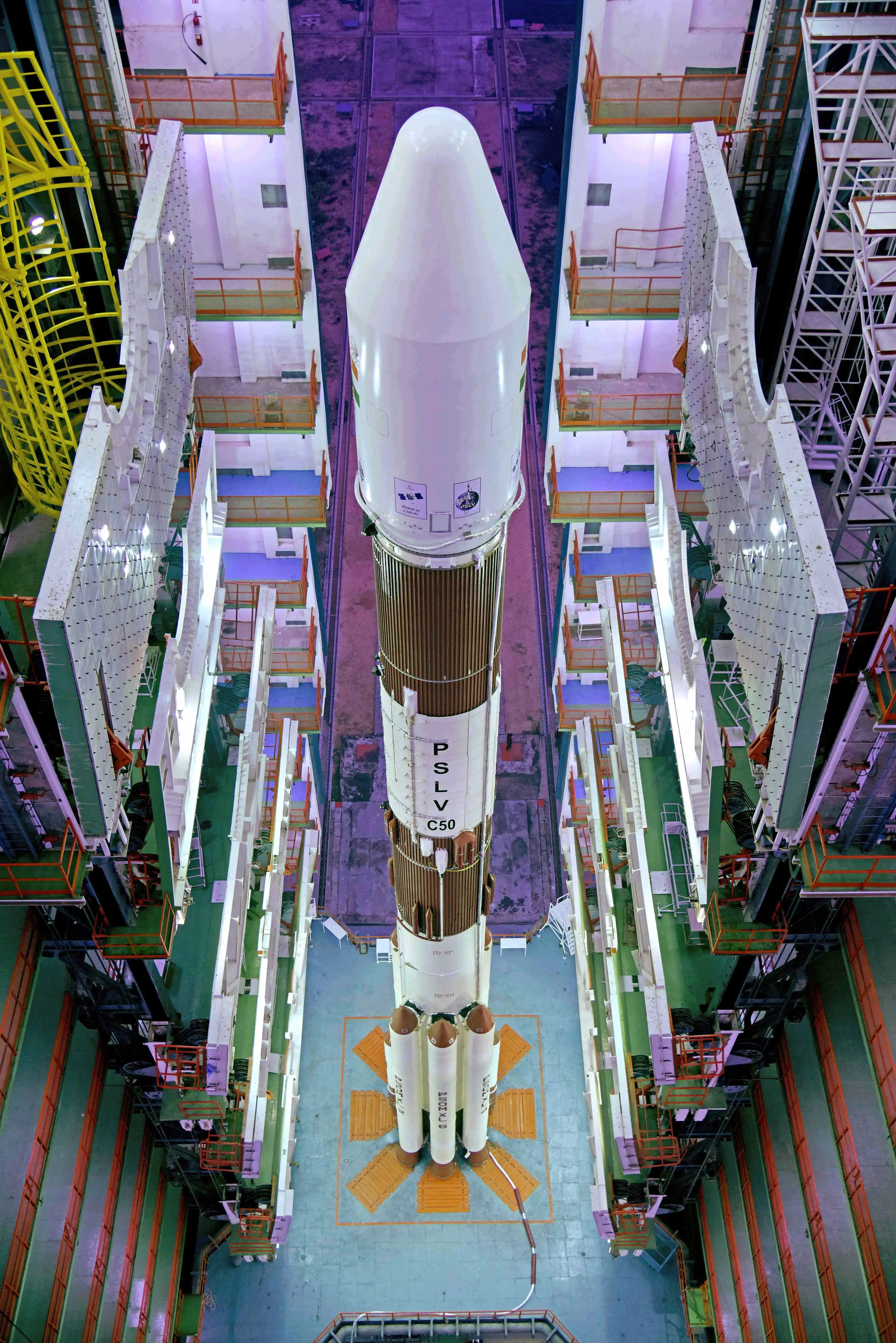
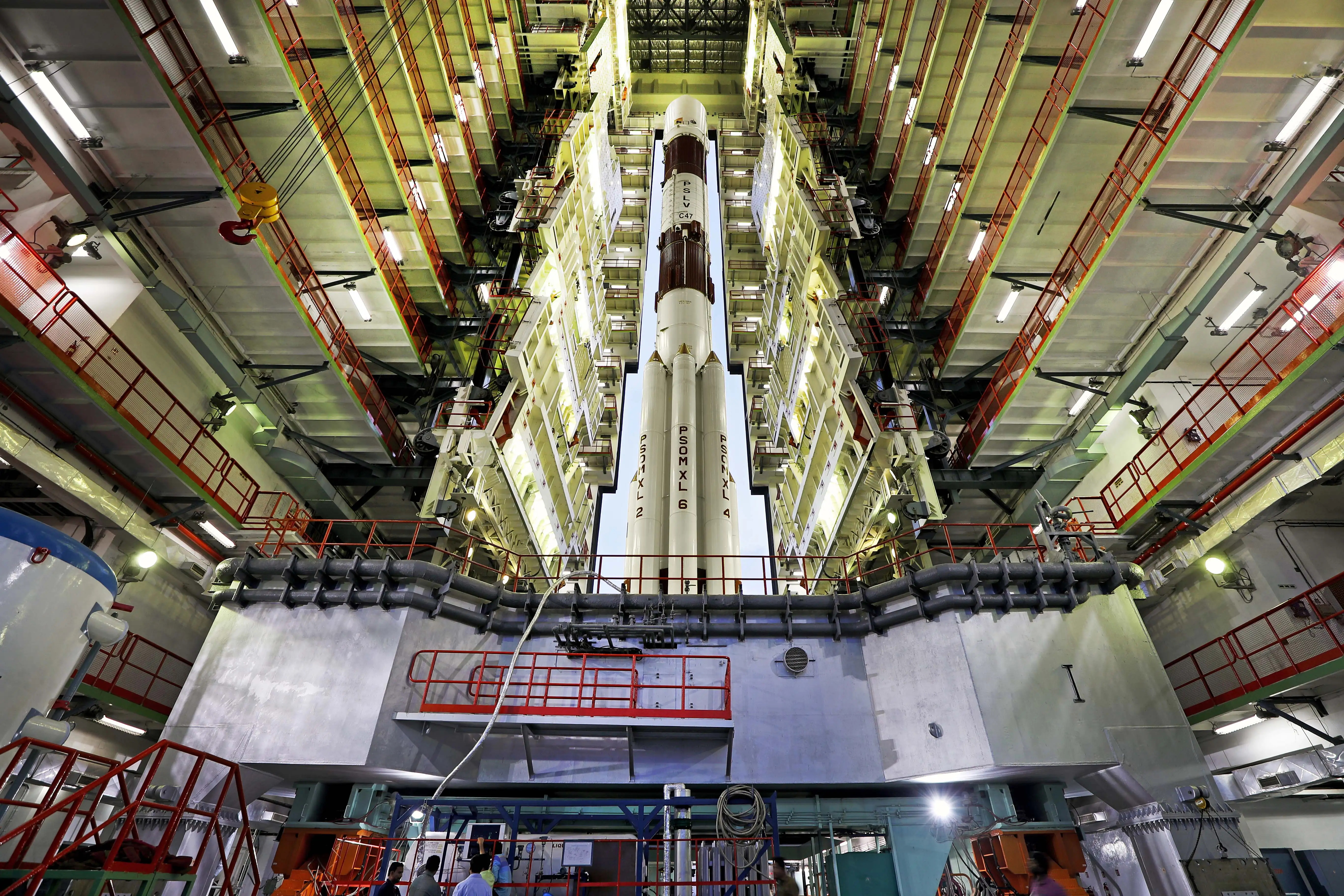
Following its description, this launcher comprises four stages, alternating propulsion systems running on solid and on liquid propellants. When needed, strap-on solid rocket motors, or side boosters, increase the PSLV’s capabilities and give place to different variants of the launch vehicle. Presently, NSIL commercializes only two of them: the core alone (CA) variant, and the six extended side-booster (XL) variant. Others existed, and it is worth mentioning the one named G, also known as the generic variant, used six side-boosters, but smaller.
On the other hand, it is worth noting that the nomenclature PSLV-D# and PSLV-C## indicate the number of developmental and operational flights, respectively.
Achievements And Notable Flights
PSLV’s first flight took place on September 20, 1993, though it ended up being a failure. After that, its track record became quite good, achieving high reliability. On a different note, this vehicle is capable of launching multiple satellites at once, and into different orbits. As a matter of fact, it set a record during the C37 flight on February 15, 2017, by orbiting 104 satellites (later on, SpaceX broke it with its Falcon 9 in the Transporter-1 mission).
To its credit, this rocket performed some notable launches, such as Chandrayaan-1 (a lunar probe) in 2008, the Mars Orbiter Mission in 2014, Astrosat (a space observatory) in 2015, and satellites for Navigation with Indian Constellation from 2013 to 2023.
In the next sections, all of the different propulsion stages (PS) are described in detail.
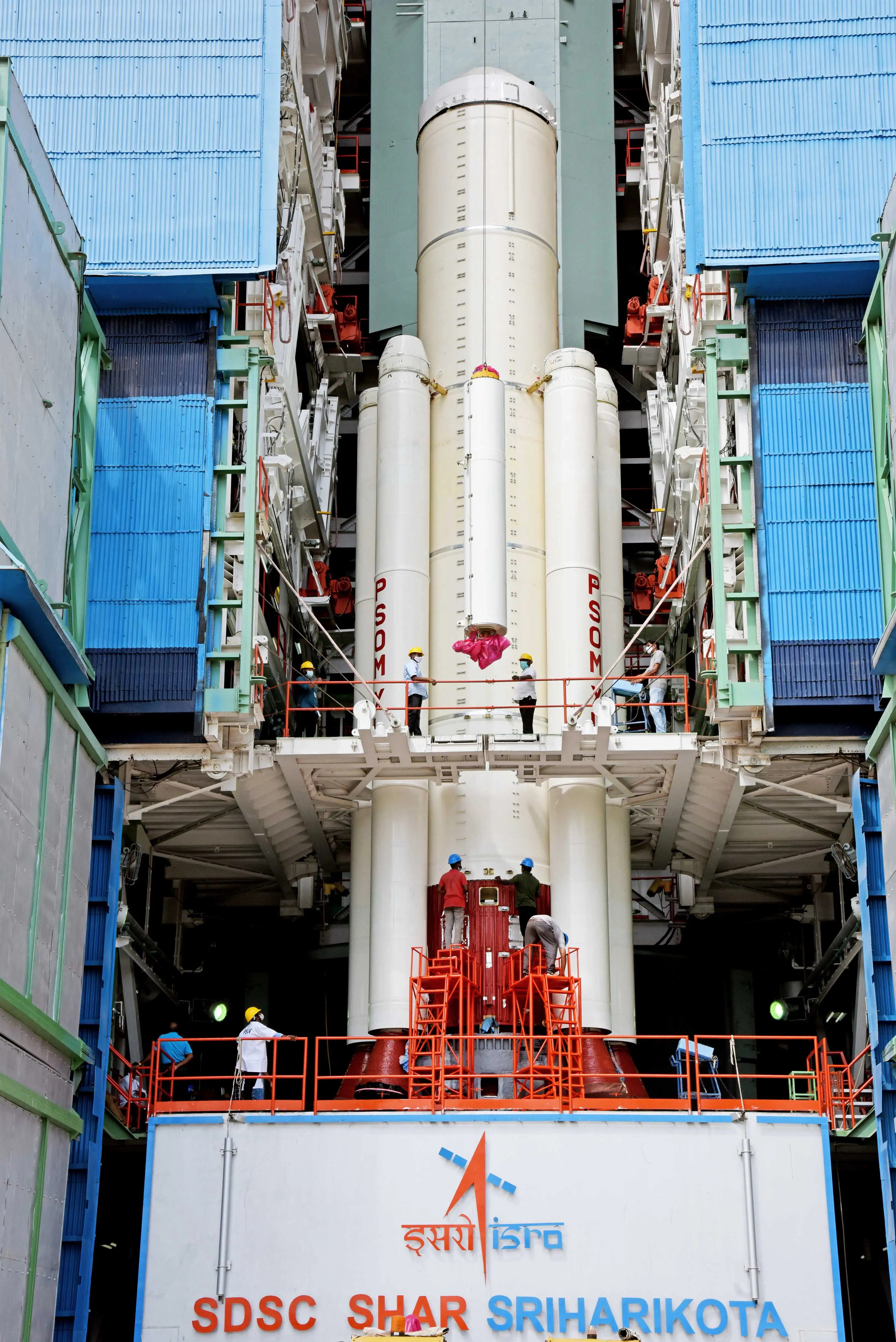
Side Boosters
Their structure is made of steel, and each of them is attached to the first stage through four points: two near the top, and two near the bottom. Instead of using auxiliary rocket motors, they complete their separation by means of spring pushers. In the XL variant, not all of the six side boosters are lit on the ground, but four of them are, with the remaining two igniting mid-flight. Finally, they are denominated PSOM XL (propulsive strap-on motor extended length, presumably), and their nozzles are of the fixed type. Two of them make use of a SITVC system analogous to the one described for the PS1, for roll control augmentation.
| Length [m (ft)] | 12 (~39) |
| Diameter [m (ft)] | 1 (~3) |
| Motor | 1x S12 |
| Propellant | Solid: HTPB(1)-bound Al(2) oxide, and AP(3) |
| Propellant mass [kg (lb)] | 12,200 (~27,000) |
| Max. thrust [kN (lbf)] | 790 (~178,000) |
(1) Hydroxyl-terminated polybutadiene
(2) Aluminum
(3) Ammonium perchlorate

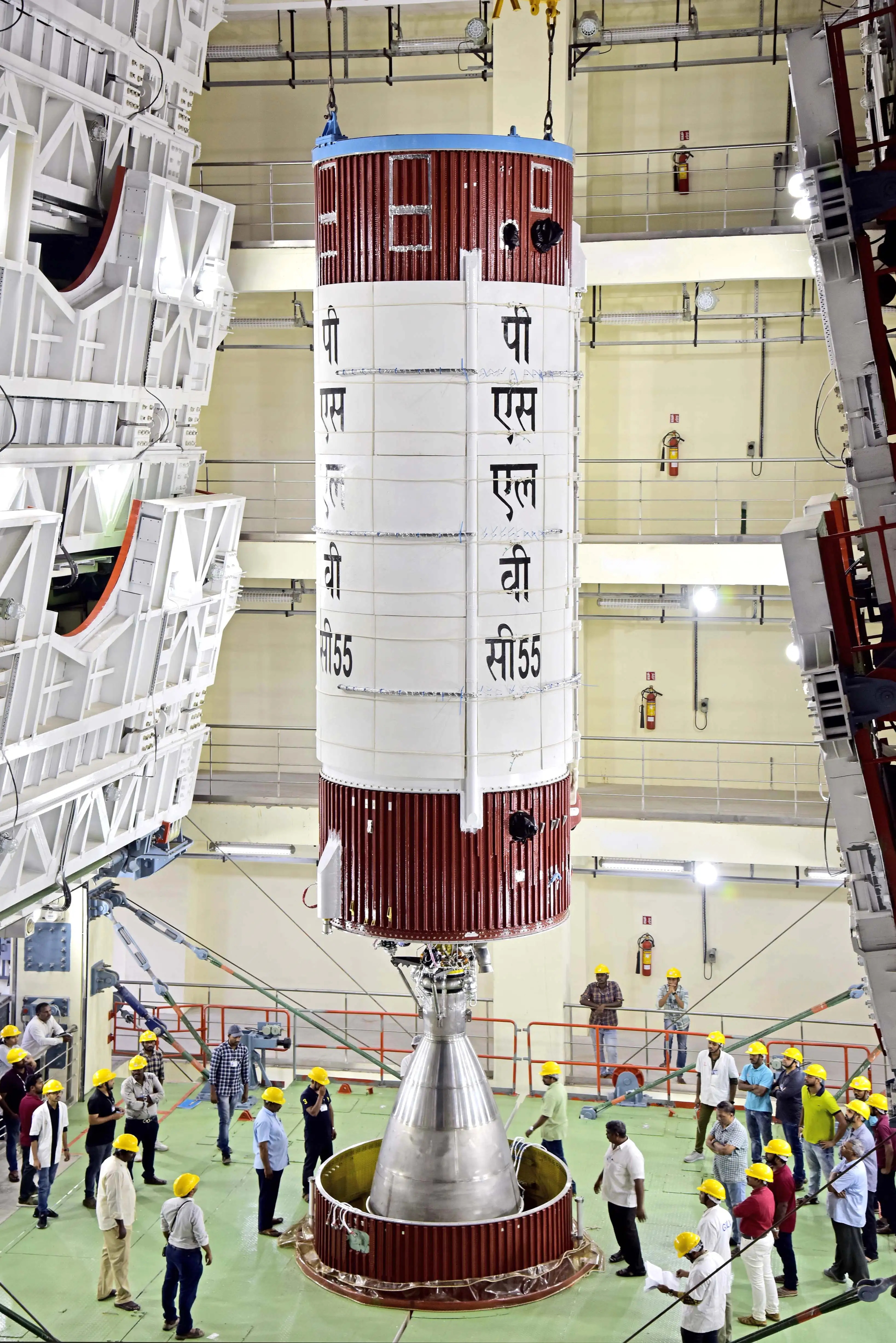
PS1 — First Stage
The first stage of the PSLV rocket is, in brief, a very large solid propellant motor made of a steel structure. Given that the nozzle in its lowest part is non-gimballing, the stage needs another control system. A Secondary Injection Thrust Vector Control (SITVC) system creates differential forces basically by injecting a liquid through the nozzle’s walls. As a result, one side of the nozzle generates higher thrust than the other, allowing the launcher to pitch and yaw. In order to roll, the launch vehicle fires control engines located under the SITVC tanks, in opposite places around the fuselage.
| Length [m (ft)] | 20 (~66) |
| Diameter [m (ft)] | 2.8 (~9) |
| Motor | 1x S139 |
| Propellant | Solid: HTPB-bound Al oxide, and AP |
| Propellant mass [kg (lb)] | 139,000 (~306,000) |
| Max. thrust [kN (lbf)] | 4,800 (~1,080,000) |
An interstage is bolted to the top of the first stage, leaving enough room for the second stage’s nozzle, but also housing retro-rockets motors. These are four pairs of solid motors used only when stage separation happens, ensuring stage one takes distance from stage 2.
PS2 — Second Stage
Made of aluminum alloy, the second stage’s (also designated PL40) fuselage doubles up both as propellant tanks with a common bulkhead delimiting them, and as structure. Painted in deep Indian red, the PS2 presents another two interstages connecting to the contiguous stages. The lower one houses a single pump-fed Vikas engine, while allowing to externally mount a series of motors. Specifically, these are four retro-rockets — for staging 2-3 — and four ullage rockets — after staging 1-2, for propellant settling.
| Length [m (ft)] | 12.8 (~42) |
| Diameter [m (ft)] | 2.8 (~9) |
| Engine | 1x Vikas |
| Propellant | UH25 + N2O4 |
| Propellant mass [kg (lb)] | 42,000 (~93,000) |
| Max. thrust [kN (lbf)] | 799 (~180,000) |
Particularly, the main engine of this stage is derived from the French Viking engines, and works under a gas generator cycle. It uses hypergolic propellants, and its ability to gimbal around two axes grants the PS2 both pitch and yaw control. A separate roll control system uses hot gas bled from the gas generator for this purpose.
Water from a toroidal tank refrigerates the gasses coming out of the gas generator and before entering the turbopumps. Gaseous helium pressurizes both propellant and water tanks
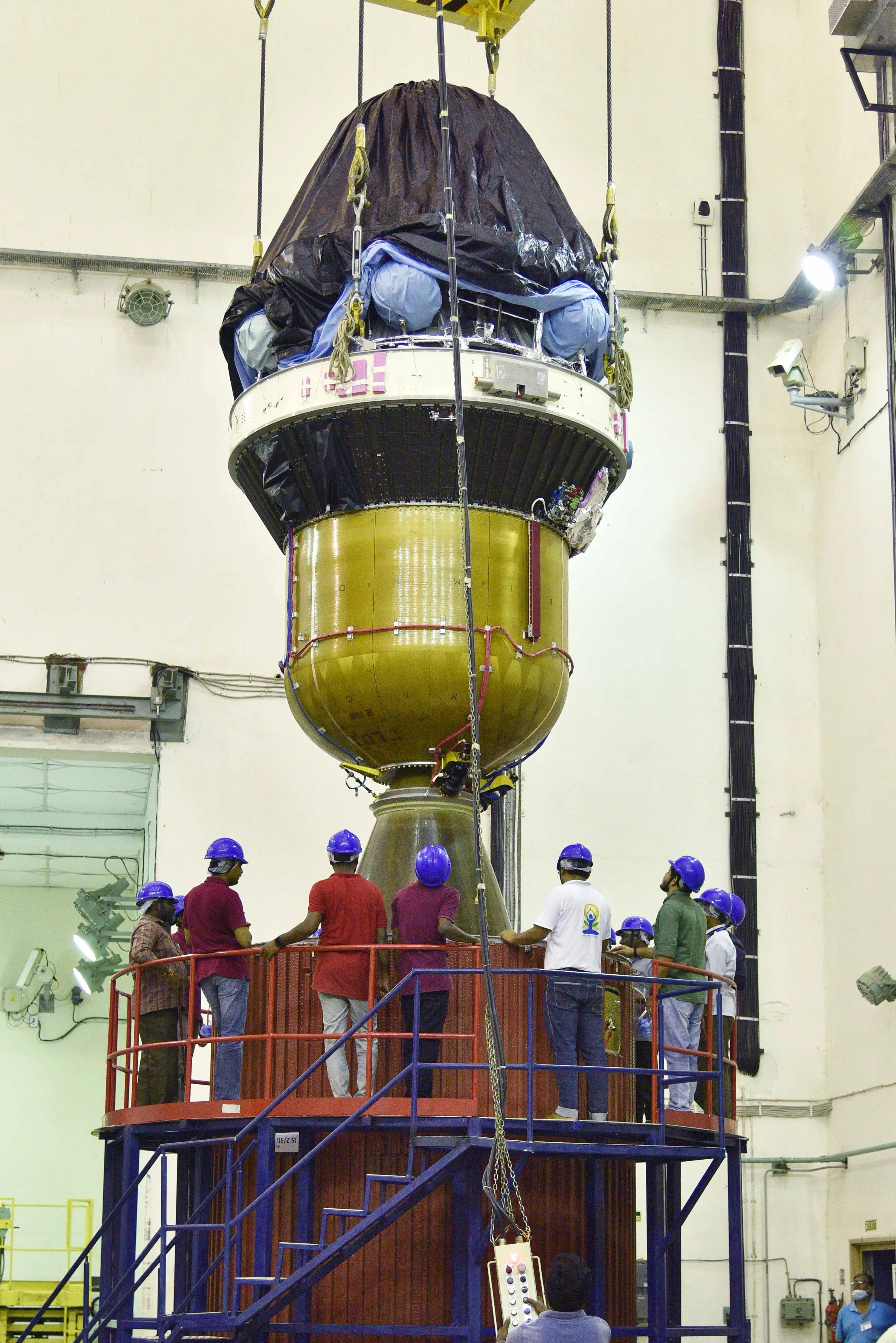
HPS3 — Third Stage
| Length [m (ft)] | 3.6 (~12) |
| Diameter [m (ft)] | 2 (~7) |
| Propellant mass [kg (lb)] | 7,650 (~16,900) |
| Motor | S7 |
| Propellant | Solid: HTPB-bound Al oxide, and AP |
| Max. thrust [kN (lbf)] | 240 (~54,000) |
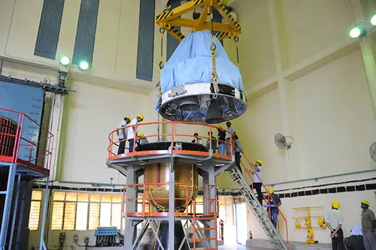
With the “H” meaning high performance, stage no. 3 runs on solid propellants, similarly to the PS1. Conversely, the casing of this stage’s motor is not also its fuselage, but the former — made in a composite material using kevlar fibers — is placed inside the latter. More precisely, it is in fact an interstage connecting the upper interstage on the second stage to the fourth stage. A black, conical structure links stages three and four, as can be seen in a picture below.
A flex, gimballing nozzle — providing pitch and yaw control (±2° of each) — remains equally hidden inside the mentioned interstage, and discharges the combustion products generated in the solid motor. It performs with increased efficiency owing to the carefully contoured, slight bell shape of its design.
Unlike the other stages, this one makes use of the reaction control system (RCS) present in the fourth stage to achieve roll control. Moreover, this RCS also becomes active for control in coast phases.

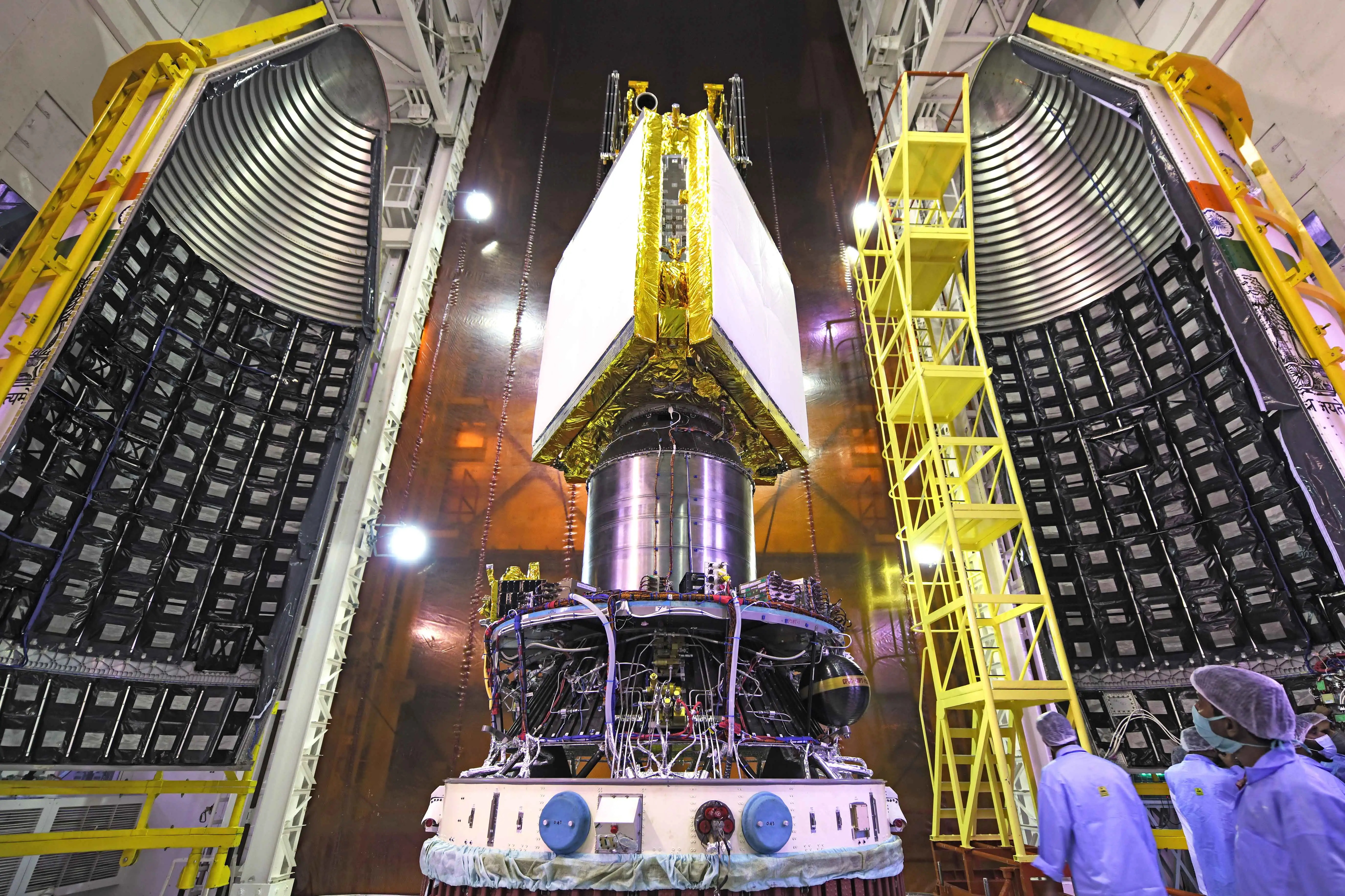
PS4 — Fourth Stage
A ring usually painted white, enables stage four to sit on top of the rest of the rocket. A pair of engines running on hypergolic propellants serve as the main propulsion source for this stage, as well as give complete control. In this case, gimballing them ±3° provides pitch, yaw, and roll for this stage. The PS4 is where the equipment bay (EB) is installed, i.e. around the propellant tanks — the metallic cylinder in the center. Two packs presenting three thrusters each are located on opposite sides of the mentioned white ring, allowing for control during coast phases (also for stage three). Furthermore, antennae located there make it possible for the vehicle to communicate with the ground to monitor vehicle and payload health, and flight status. To this end, telemetry is transmitted on S-band, and transponder signal on C-band.
| Length [m (ft)] | 3 (~10) |
| Diameter [m (ft)] | 1.34 (~4.4) |
| Engine | 2x |
| Propellant | MMH(1) + MON3(2) |
| Propellant mass [kg (lb)] | 2,500 (~3,500) |
| Max. thrust [kN (lbf)] | 14.6 (~3,300) |
(1) Mono-methyl hydrazine, fuel.
(2) Mixed Oxides of Nitrogen, oxidiser.
A circularly shaped shelf-like structure is the aforementioned EB, where the brains of the rocket certainly reside. That is, the inertial navigation system (INS), telemetry electronics, safety systems, and other equipment boxes. Additionally, secondary payloads can be deployed from here.
Another very important feature of the PS4 is its reigniting capability, which lets the launcher place payloads into different orbits. After the end of the mission, the stage vents all pressurized fluids to become passivated, minimizing the risk of a break-up, and consequently avoiding to generate space debris.
PS4 As Orbital Platform
In addition to all of this, the fourth stage of the PSLV is capable of working as an orbital platform (OP). Flights C37, C38, and C44 saw trials of this option, while C45 added an independent power source — a fixed solar array on the tank. Finally, on flight C53 it took the official denomination of orbital platform experiment module (POEM).
Payload Fairing
Also referred to as “heat shield,” the payload fairing allows the launcher to carry multiple payloads in tandem using the Dual Launch Adapter (DAL), or other adapters for smaller satellites. It consists of two halves made of aluminum, with the cylindrical segment machined in order to obtain isogrid construction. These halves use a pyrotechnical system in order to separate from each other, and from the fourth stage. Acoustic blankets are sometimes present inside the fairing for the purpose of protecting the payload from vibrations of that nature, especially at liftoff.
| Length [m (ft)] | 8.3 (~27) |
| Max. diameter [m (ft)] | 3.2 (~10) |
| Mass [kg (lb)] | 1,182 (~2,600) |