


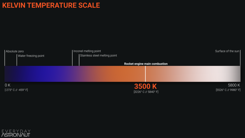
Gases inside an engines combustion chamber can reach ~3,500 K – which is about half as hot as the surface of the Sun – certainly above the melting point of most materials. Engines need to reach this temperature in order to function correctly, but how can they survive this? In this article you will learn about engine cooling methods used to keep rocket engines from melting.
Heat Sink
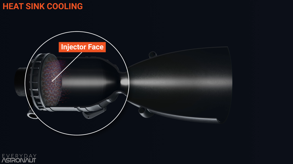
At the top of a combustion chamber sits the injector face. Here, the fuel and oxidizer are pumped into the chamber at extremely high pressures. The fuel and oxidizer mix inside the chamber and begin to ignite. As long as the flow continues, the propellants will continue to combust and ignite. But how do the metal chamber walls not melt as the hot gas passes through?
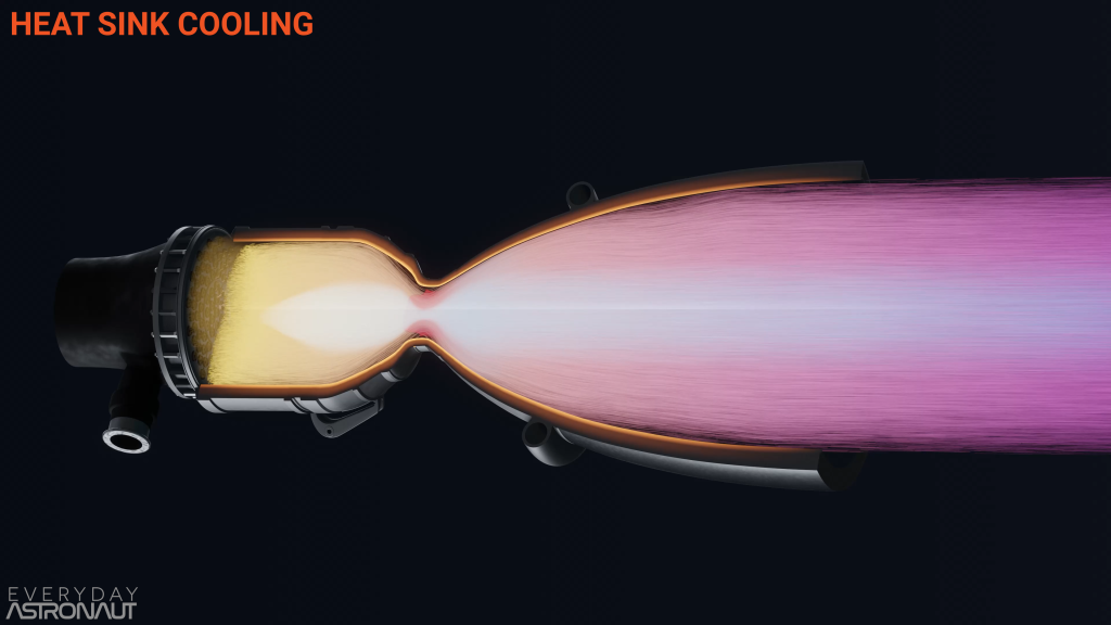
One option could be to make the walls thick, so much so that the hot gases can’t heat up the thick layer of metal enough to melt it. Here the walls act as a heat sink – that is a large thermal conductor, which is capable of handling high heats for a period of time before all the metal reaches boiling point. An exotic material, one that can handle high heats and stay strong, like inconel or another alloy, could be a good option for this.
However, heat sinks have several major limitations. One limitation is weight. Weight reduction is extremely important when building a rocket, and an additional thick metal wall is going to add a lot of extra weight. Another issue is that an engine will only be able to run for so long before all of the metal eventually reaches its melting point.
This means that heat sinks are not a great option for main propulsion engines, which need to run continually for several minutes. However, they could be a viable option for smaller engine types like maneuvring thrusters. Maneuvring thrusters run for a much shorter time than the main propulsion engines, and are often pulsed, giving the engine an opportunity to cool down in between pulses.
Fuel Oxidizer Ratio
Another option to keep an engine from melting is to run the engine in a fuel rich or oxidizer rich configuration, which will lower the temperature of the main exhaust. This ratio is known as the fuel to oxidizer mass ratio.
If someone wanted to burn all of your propellant and have all of it react with each other, you need to burn it at their stoichiometric ratio. Stoichiometric ratio is where the complete amount of fuel and oxidizer perfectly react with each other so no propellant is left unburnt. This means that each atom of each molecule will react with one other atom for complete combustion. The result of this is that you release the maximum amount of heat from the chemical bonds as possible, which would be great in some situations, but not when dealing with rocket engines. The more heat a rocket engine produces, the more you will have to cool your engine so it doesn’t melt, which is not ideal.
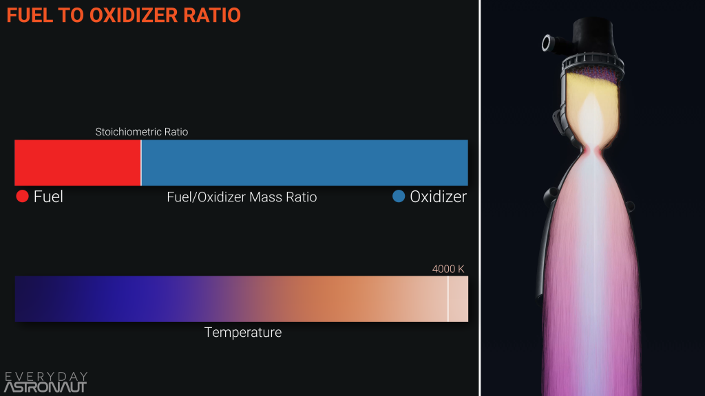
This means that rocket engines have a fuel to oxidizer ratio slightly off from stoichiometric. An engine’s main combustion chamber will tend to run fuel rich as this will have a lower thermal load and have high efficiency.
You could also run the pre-burner or gas generator fuel rich to keep it cool, which is important as it is extremely hard to cool a spinning turbine. The turbine will have a set amount of heat that it can take based on its materials, so the fuel oxidizer ratio needs to change to be suitable. Turbines can be designed to run fuel or oxidizer rich, like the Space Shuttle’s RS-25 main engine, which ran fuel rich, or the soviet designed NK-33 engine, which ran oxidizer rich propellant through their closed cycle pre-burners.
Ablative Cooling
Ablative cooling is one of the most simple and effective ways of cooling an engine. This method uses a material which will vaporize and then get thrown away, taking the heat with it. This is usually made out of carbon composite which has an extremely high melting point.
This is the same method that most spacecraft use for heat shields. When a spacecraft re-enters the atmosphere it gets very, very hot. The heat shield takes this heat, and when it’s surface gets too hot, it melts a layer away, taking the heat with it. This stops the heat from penetrating deeper into the spacecraft.
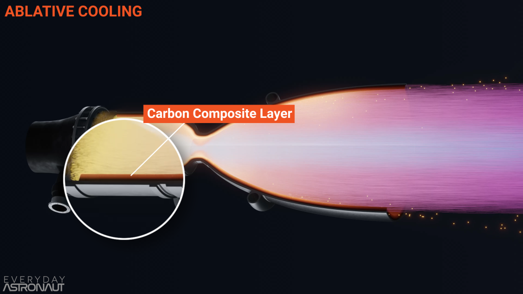
This same principle can be applied to cooling a rocket engine. Inside the walls of the combustion chamber and nozzle is a layer of carbon composites. When the propellant is burning in the engine, this carbon layer will slowly be burnt off. This method has no moving parts and is self-regulating, which makes it an extremely efficient and reliable method for cooling engines.
But there are some limitations, most obviously that an engine cooled this way can’t be reused. Some engines won’t even be able to go through full testing before being used as it wears down the ablative chamber walls. Most famously, the Apollo Lunar Ascent engine couldn’t be test fired as a complete unit until it was fired on the surface of the moon to take the astronauts home!
There are a couple of other examples of ablatively cooled engines, including SpaceX’s first Merlin engine, the Merlin 1A, which flew on the first two Falcon 1 flights, and United Launch Alliance’s Delta IV engine, the RS-68A. It is easy to see that the RS-68A engine is ablatively cooled as it runs on hydrolox, which has a completely transparent exhaust of water vapor – the same as the space shuttle. However, the RS-68 has a bright orange exhaust due to the carbon which is ablated and ejected from the engine as it continues to react with the oxygen in our atmosphere.
Another type of small engines, reaction control thrusters, can also use ablative chambers, as this type of engine is only used for a short duration and has a set amount of propellant it can burn through before running out. This means engineers can design the thickness of the wall to match the maximum use.
Regenerative Cooling
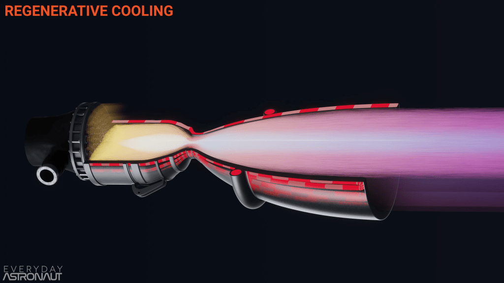
Regenerative cooling is the most common way to stop a liquid fueled rocket engine from melting. This method entails flowing some or all of the propellant through the walls of the combustion chamber and nozzle before going through the injectors and into the chamber. While the walls and nozzle of rocket engines look thin, there are actually small channels in the walls, which fuel can be run through in order to keep them cool.
The discovery of this was a major breakthrough, as this method allowed rocket engines to run more or less indefinitely. The early versions of regeneratively cooled engines have a main chamber and a liner on the outside of the engine, where the coolant or fuel could run through. After this, it was normal to see pipes used as the walls of the combustion chamber. An example of this is the RL-10 engine, which still uses a brazed tube construction.
A more common practice today is to cut a cooling channel in the wall of the nozzle, then use a copper or nickel alloy to seal it off, which then will be the inner wall of the chamber. Copper and nickel alloys are used here because of their high thermal conductivity, which allows them to transfer heat from the wall into the coolant.
This method means that the fuel can boil before reaching the chamber. This process can sometimes be used to spin the turbine to run the pumps of the engine – this is the expander cycle. The cycle harnesses energy from the thermal expansion of the fuel going from liquid to gas to spin the pumps.
The majority of engines use fuel as their coolant, but oxidizer is also an option. When a cryogenic propellant is used, the outside of a rocket nozzle will be extremely cold, while the inside of the wall will be extremely hot.
One of the main challenges with regenerative cooling is that the pressure inside the walls has to be higher than the pressure of the combustion chamber. This is due to the walls simply being tubes that feed the injectors, and as pressure always flows from high to low, the injectors need to have higher pressure than the combustion chamber.
With an extreme amount of pressure inside tiny walls, it is easy to imagine that a leak could happen. Luckily, because the pressure inside the wall is higher than the pressure in the chamber, if there were a leak it would just provide extra cooling due to film cooling.
Film Cooling
The next common method of engine cooling is film cooling. This method is where a fluid is injected between the combustion chamber and nozzle surface, and the hot combustion gases. As fluids are either gas or liquid, this can be done with liquid or gaseous propellants. The purpose of this is to create a boundary between the wall and the hot combustion gas, which will act as thermal insulation with a cooler fluid in between them.
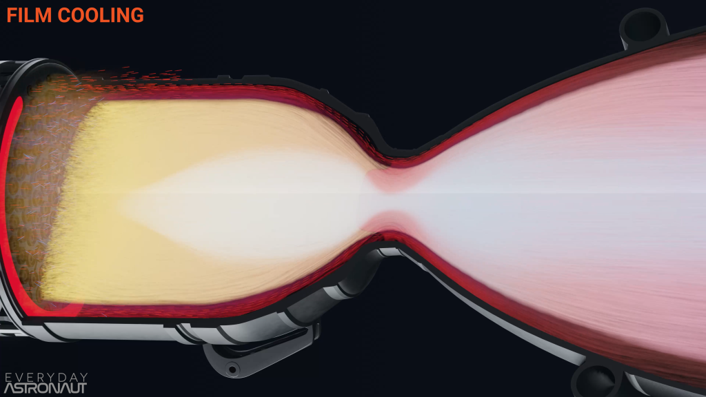
The easiest way to do liquid film cooling is to have a higher concentration of fuel or oxidizer injectors on the outer perimeter of the injector face. As the main combustion chamber is fuel rich, fuel is usually favored – there will be a ring of extra fuel flowing around the outer perimeter that won’t have the right amount of oxidizer needed to react with. This means there will be a ring of fuel rich combustion to stop the heat from transferring from the main combustion gases to the walls.
The majority of the fuel close to the wall that won’t react due to the lack of suficient oxidizer essentially runs along the walls of the chamber as a film, between the combustion gases and the chamber walls. However, it will probably phase change from a liquid to a gas, creating a vapor boundary layer, which will continue to absorb heat as the process of changing phases absorbs a certain amount of heat.
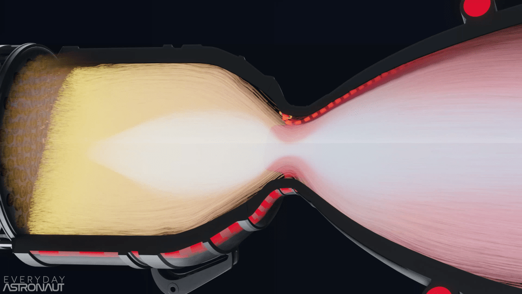
It is also common to drill holes into the wall (provided they are regeneratively cooled) and leak in a small amount of liquid fuel, specifically in hotspots like the throat of an engine.
A benefit of using fuel as coolant is that it creates a carbon layer, in the form of coking, along the walls when a carbon based fuel like RP-1 is used. In fuel rich combustion, a lot of carbon is left unburnt and can create soot. You can see this in the exhaust of the gas generator for the Merlin engine. In this engine, SpaceX runs the gas generator extremely fuel rich, which reduces the temperature enough to stop the turbine from melting. The result of this is a very dark and sooty exhaust. This soot can also stick to the inside walls of the chamber. It is not great if the soot sticks to the injectors and the cooling holes, but the soot which sticks to the walls can act as an additional thermal barrier.

The exhaust gas of the Merlin engine’s gas generator can also be used to film cool some of the nozzle. This doesn’t happen on the sea level Merlins, where the exhaust is just dumped overboard, but it does happen on the vacuum optimized Merlin. Here, the turbine exhaust gas gets pumped into the nozzle extension, which optimizes the engine for vacuum conditions. As the nozzle expands after the throat, the exhaust gas gets cooler and has a lower pressure the further down the nozzle you travel. When pumping in the turbine exhaust gas, it needs to be done far enough down the nozzle where it has a higher pressure than the main combustion exhaust pressure, but also at the point where the heat needed to protect the nozzle can successfully be insulated by the film cooling of the turbine exhaust gas as regenerative cooling is often terminated at that point.
This doesn’t only happen on the vacuum optimized Merlin, but has been done on both of the engines on the Saturn V. The F-1 and the J-2 both used turbine exhaust film cooling to keep the lower portions of their nozzles cool. While the J-2 still used regenerative cooling below the manifold, the F-1 stopped doing regenerative cooling at the manifold as film cooling was enough to stop the rest of the nozzle from melting.
The effect of this was visible when the F-1 engines were running. The bright orange flame front didn’t start at the end of the nozzle, there instead is a dark part between the flame and the nozzle exit – this is the film cooling turbine exhaust. Because of it being so fuel rich, it takes a moment for it to find oxygen to burn with and ignite, which doesn’t happen until it has left the engine and can start to react with oxygen in the atmosphere.
Radiative Cooling
Both SpaceX’s vacuum Merlin engine and Rocket Lab’s vacuum Rutherford engine glow bright red when powered, because the metal gets really hot and radiates the heat out into space. As there is no atmosphere in space, there is no air to pick up and conduct or convect heat away. Instead, engines can radiate heat away from their nozzles, as radiation doesn’t require matter to transfer heat – like the Sun that transfers heat through the vacuum of space via radiation.
The nozzle extensions in the vacuum optimized Merlin and Rutherford engines are made from a very thin metal, usually an alloy like niobium alloy, which is able to withstand high heat loads. The downside of these nozzle extensions though is that they are very thin and relatively fragile. Furthermore, niobium is also very reactive to oxygen, which means the engine like this can realistically only operate in a vacuum environment and is also more complex during manufacturing.
Summary
Looking at the Merlin Vacuum engine is perhaps the best way to summarize methods of engine cooling, as this engine employs almost every type of cooling.
The gas generator uses both a heat sink and a very fuel-rich exhaust. This is done as the other types of cooling can’t be used for a spinning turbine. In this situation, engineers just have to use high temperature tolerant metals and lower the exhaust temperature so that the metal can handle the heat.
Regenerative cooling is used for cooling the chamber walls, throat and the first section of the nozzle, and for the inside of the engine, some film cooling is done. Film cooling with the gas generator exhaust at the nozzle extension is utilized when the regenerative cooling channels end. Additionally, the nozzle extension also radiates additional heat away by glowing bright orange using a niobium alloy.
The vacuum optimized Merlin engine doesn’t appear to use ablative cooling, but as the upper stages are only used once, the engine could probably even have used ablative cooling if it were necessary.
So, what I read here clearly means Tom Markusic was running fuel-rich to be cool(er)?
Jokes aside, this is wonderful writeup, with examples and visualisation. Thanks and keep up the good work!
Another means of cooling is the “magnetic nozzle” which keeps hot plasma away from the engine walls with a magnetic field. Typically, this is done by wrapping a solenoid coil around the exhaust. A prominent existing user of this technique is the VASIMR engine developed by Dr Franklin Chang Diaz and extensively tested, but if memory serves, some other electric propulsion devices use this as well.
Very interesting! (I was going to say cool, but I didn’t want to leave a bunch of soot in the comment box.)
Very well explained, thank you.
One thing that intrigues me. At the beginning of the article it says:
“An engine’s main combustion chamber will tend to run fuel rich as this will have a lower thermal load and have high efficiency.”
What does high efficiency mean here? I know it’s important not to get too hot and destroy the engine, but assuming the heat could be dealt with, wouldn’t the maximum possible amount of thrust be generated at the stoichiometric fuel ratio? If so then a fuel rich (or oxidizer rich) mix would be less efficient than the theoretical maximum. Force = mass * acceleration, in this case the fuel ratio is not affecting the amount of mass being ejected, and I’m not sure about the effect of the temperature on the acceleration but using all that extra fuel for cooling means less of it is used for generating thrust and it will be used up quicker.
Wow, amazing webpage and channel! This will be my favorite resource over the summer! Thanks!
I understood that the WW2 V2 Rocket use LOX plus alcohol mixed with 30% water to keep the temperature in the combustion chamber from getting too hot during ascent.